Yes, unfortunately indeed.Unfortunately not all cap values are available in FKP series.
No. I don't know which Panasonic types are PP film/foil.vicnic have you tested Panasonic PP
The well known Panasonic PP film cap is the ECWFD series :
https://www.farnell.com/datasheets/1790618.pdf
Available now again at Mouser, so also for the EU.
A few years ago I also sent some Panasonic ECHU (PPS, SMD) to Viktor for distortion measurements.
If I remember correctly, they were some 15~20dB worse than the WIMA FKP2.
Which was fine for me, as they are much more compact and thus convenient for certain applications.
Patrick
The well known Panasonic PP film cap is the ECWFD series :
https://www.farnell.com/datasheets/1790618.pdf
Available now again at Mouser, so also for the EU.
A few years ago I also sent some Panasonic ECHU (PPS, SMD) to Viktor for distortion measurements.
If I remember correctly, they were some 15~20dB worse than the WIMA FKP2.
Which was fine for me, as they are much more compact and thus convenient for certain applications.
Patrick
Those are MKP, not film and foil. Still good caps, and I would be curious as to the result.
Not surprised with the PPS, being a higher k and metallized.
Panasonic ECQP are the FKP2 equivalent film and foil types, however, they are discontinued.
https://media.digikey.com/pdf/Data Sheets/Panasonic Capacitors PDFs/ECQP(U).pdf
Last edited:
Higher voltage capacitors of the same type usually have lower distortion. Not all types can be made in surface mount as the insulating film using some types of plastics can't take the soldering temperature. Some types will change values if overheated during soldering.
As to compensating for temperature, a better choice is to use a TEC (peltier device) to maintain a constant temperature.
As to compensating for temperature, a better choice is to use a TEC (peltier device) to maintain a constant temperature.
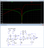
It is good, but... needs the special buffer for every frequency. Probably the software linearization curve is the easiest way for to get nice liner picture if it is so neededFor your inspiration
") .
.Vic.
How's this for an idea: some speaker crossovers have used "biased" capacitors (two in series with twice the original capacitance, with their junction going through a high-value resistance to a DC voltage source) in an attempt to improve sound. Might this lower capacitor-related distortion in an oscillator?
Using Batteries to Bias crossovers into Class A, how does it work?
Using Batteries to Bias crossovers into Class A, how does it work?
The point of biasing a crossover capacitor with DC is to optimize the use of a polarized capacitor with an AC signal, presumably to keep the capacitor forward biased all the time. In an oscillator, this does not happen - only non-polar capacitors are used.
With non-polar caps, especially miniature multi-layer C0G capacitors, adding extra DC bias can add even order nonlinearities, by making the peak field strength across the dielectric higher for one polarity of signal peak vs. the other polarity. This is only an issue with multilayer ceramics, where the dielectric is already exposed to extremely high field strengths, since the dielectric layers are so thin. The theory is that the dielectric starts to saturate at extremely high field strengths, and biasing the cap away from a net zero field strength makes the peak levels worse and also asymmetric relative to the AC signal across the cap.
A nice side effect of this behavior is that one can use this to determine the linearity of an MLCC dielectric in a distortion test by changing only the field strength across the dielectric, without changing the generator level and analyzer levels (which would alter the analyzer fundamental). If you see a change in 2nd harmonic while changing only the DC bias, you have found a nonlinearity caused by dielectric saturation. Presumably, if the same amount of 'squish' happens at a higher DC bias level for one cap compared to another, that's a cleaner cap.
For your inspiration
Nice! I like this idea. I toyed with the thought myself, of electronically compensating for the twin T droop with a peaked high-pass filter, but never implemented it. A key nice thing about it is that the filter amplifier does not see the fundamental to any extent, so it does not introduce distortion.
In the real world, of course, this idea competes with, and needs to be compared to, the positive-feedback active twin T circuit (where some worry about the amplifier being in the signal path and contributing to distortion).
I also note that, while the passives in the twin T itself must be quite precise, the passives in this compensating part of the circuit are not that critical.
Cheers,
Bob
I figured out a way to tweak software to do the correction- if your software supports a correction file (like a mike cal file). Plot the response of the notch and manually adjust the correction curve it at the notch frequency back to zero or some arbitrary level correction. It will then correct for the harmonic attenuation with a complementary curve. you could have curves stored for several notch filters.
That boosts the fundamental which may or may not be desired.
Edit the file. It's a text file.
The point of biasing a crossover capacitor with DC is to optimize the use of a polarized capacitor with an AC signal, presumably to keep the capacitor forward biased all the time. In an oscillator, this does not happen - only non-polar capacitors are used.
But it IS (also) done with nonpolar caps. Some of the following reads a little like woo (there's no literal crossover distortion as there is in a Class B amp), but it's interesting regardless:
http://www.lansingheritage.org/images/jbl/specs/home-speakers/1993-k2-s5500/page11.jpg
- Home
- Design & Build
- Equipment & Tools
- Low-distortion Audio-range Oscillator