what's the real schematic of this dac's i/v stage?what's the schematic of lm4562 amp?Is that a classic i/v amp?Is that a buffer for a resistor as a load for iout dac?
Dear Dreamth,
We are here (this forum; this planet) to learn and we learn through experience (experimentation) so do not dismiss options until you try them. Some of us do not tolerate the "sound" of opamps anymore. They suck the life of the music.
Simple (low noise; low capacitance low inductance) resistor is best for TDA1543 (no slew), as -EC- taught us with his honeycomb resistors, then for TDA1541A comes the expensive Tx, then the simple discrete solution which better have "Low Thermal Memory Distortion" (LTMD) circuit or use 2SK30A, about which Hephaïstos (ascended Master) found it shows lowest TMD. 😎
The idea is enjoy the breath of music again.
Low THD and high slew rate means nothing if the sound is sterile...
Cheers,
M
PS: I am sure -EC- can invent something even better. 😀
Hello
How about tube I/V output ?
Thank
Bye
Gaetan
They are wav format files, intended to be written as audio CD or played back by some PC media player through an USB/I2S interface. The DC level at the output of the DAC is indeed fs, fs/2, f2/4, fs/8, etc. with a 3-step variation superimposed. (fs = full scale)I also tried your files but with no luck.
All of the tracks except track 15 produced a - full scale DC at the output of the DAC. Track 15 only noise.
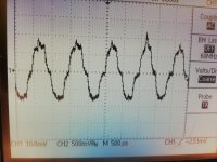
On a low resolution or noisy system the 3-step variation is buried in the noise. Therefore you need a x100 low noise amplifier for visualization.
--------------------------------------
Sorry I should have added that the x100 low noise amplifier should be AC coupled, to show only the 3-step variation (that should be even in + and - directions referring to the center line)
Last edited:
It is before the x100 amp directly at the output of the I/V stage that the .wav files 1-14 produces steadily full scale - DCThey are wav format files, intended to be written as audio CD or played back by some PC media player through an USB/I2S interface. The DC level at the output of the DAC is indeed fs, fs/2, f2/4, fs/8, etc. with a 3-step variation superimposed. (fs = full scale)
On a low resolution or noisy system the 3-step variation is buried in the noise. Therefore you need a x100 low noise amplifier for visualization.
--------------------------------------
Sorry I should have added that the x100 low noise amplifier should be AC coupled, to show only the 3-step variation (that should be even in + and - directions referring to the center line)

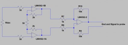
what's the real schematic of this dac's i/v stage?what's the schematic of lm4562 amp?Is that a classic i/v amp?Is that a buffer for a resistor as a load for iout dac?
Classic OpAmp I/V stage with 2K from output of opamp to inv.input and noninvert to ground.
x100 amp noninverting 100k from out to inv. input and 1 k to ground. Yes I know it is not exactly x100...
I shall experiment with some LPF to get rid of some of the noise.Koldby,
What about the idea of placing a 22nF cap par. to the output resistor, that would suppress noise quite a bit, just for testing.
What I don’t understand is where all this noise comes from.
You could also feed the Dac with only digital zero, and try to find the source of this noise, an idea ?
Hans
What I cannot understand is you can get such a clean signal, if you in fact are measuring on a NOS DAC without any filters , digital or analog. Should be far more noise then IMHO. Do the AP have lowpass filter switched in?
You better make a low noise cascoded transconductance stage for a clean amplification, or something like the ones discussed here:Classic OpAmp I/V stage with 2K from output of opamp to inv.input and noninvert to ground.
x100 amp noninverting 100k from out to inv. input and 1 k to ground. Yes I know it is not exactly x100...
dac I/V convertion with very low distortion
I thought you liked discrete , non global feedback designs too...they are not very low thd , but for signal measuring they clearly are better.
To clearly measure whats there at 100x gain with a classic virtual ground i/v you need something like ths4631, with very low current noise and high bandwidth.
So I found the main reason for the excessive noise.Koldby,
What about the idea of placing a 22nF cap par. to the output resistor, that would suppress noise quite a bit, just for testing.
What I don’t understand is where all this noise comes from.
You could also feed the Dac with only digital zero, and try to find the source of this noise, an idea ?
Hans
A faulty earth connection in a RCA plug caused most of the noise. 22nF over the feedback I/V and a LC filter just before the x100 amp did the rest, so now it is more clear. Still not as clear as your measurements, but clearly three steps.
Can you make a file that shows the same, but for 17 bit resolution? Would that be -96,31 dB?
Attachments
Let me first answer your question how I measured.So I found the main reason for the excessive noise.
A faulty earth connection in a RCA plug caused most of the noise. 22nF over the feedback I/V and a LC filter just before the x100 amp did the rest, so now it is more clear. Still not as clear as your measurements, but clearly three steps.
Can you make a file that shows the same, but for 17 bit resolution? Would that be -96,31 dB?
It is very important to have separate digital and analogue grounds.
I even used different supplies, to keep things apart.
Since you are measuring a Nos Dac, my advice would be to leave everything working the way it is intended, and that's with an output resistor and not an I/V convertor with a virtual gnd.
So my measuring circuit started with a instrumentation amp like circuit, giviving no load on your Dac output resistor, followed by a level shifter, both having a extremely high Common mode suppression, combined with a high gain.
It is important to connect your probe to the two wires of the second op amp and not somewhere to some gnd.
This way you will get the lowest possible noise from the digital section and a clean analog signal, and still having the Nos Dac in operation as envisaged.
Your second question concerning a higher input signal, just tell me how you feed your Dac, through a CD player, or can you also use an USB input and feed a signal from your computer.
In the last case, your sound processor can produce any signal of any frequency.
Hans
Attachments
I'm not sure what signal you used, it is way better than before, that's great. But I see at least 20steps, which corresponds more or less with the 500mV/div on your scope.So I found the main reason for the excessive noise.
A faulty earth connection in a RCA plug caused most of the noise. 22nF over the feedback I/V and a LC filter just before the x100 amp did the rest, so now it is more clear. Still not as clear as your measurements, but clearly three steps.
Can you make a file that shows the same, but for 17 bit resolution? Would that be -96,31 dB?
For a 17bit resolution you would need 6dB less, which is -99,31dB.
But how do you handle that with a 16bit system ?
Hans
Jriver-USB-Wave IO-Signed Magnitude-TDA1541A.Let me first answer your question how I measured.
It is very important to have separate digital and analogue grounds.
I even used different supplies, to keep things apart.
Since you are measuring a Nos Dac, my advice would be to leave everything working the way it is intended, and that's with an output resistor and not an I/V convertor with a virtual gnd.
So my measuring circuit started with a instrumentation amp like circuit, giviving no load on your Dac output resistor, followed by a level shifter, both having a extremely high Common mode suppression, combined with a high gain.
It is important to connect your probe to the two wires of the second op amp and not somewhere to some gnd.
This way you will get the lowest possible noise from the digital section and a clean analog signal, and still having the Nos Dac in operation as envisaged.
Your second question concerning a higher input signal, just tell me how you feed your Dac, through a CD player, or can you also use an USB input and feed a signal from your computer.
In the last case, your sound processor can produce any signal of any frequency.
Hans
I do not have a sound processor that I can set to certain dB levels. The best I have is Spectrum analyzer software wit a wave generator, but only a % of full scale and its lowest % is 1%...
Not a higher input signal--- Lower. -96 dB I guess to see if the DAC can resolve 17 bits.
And I know my measuring setup is very rudimentary, but I never intended to measure at these low levels, just checking if the concept of signed magnitude actually worked. I think I will try to measure it with the Sowter transformers , when they arrive next week. I am using the small ones in the DAC (balanced NOS TDA1541A) that I use in my audio system now.
I'm not sure what signal you used, it is way better than before, that's great. But I see at least 20steps, which corresponds more or less with the 500mV/div on your scope.
For a 17bit resolution you would need 6dB less, which is -99,31dB.
But how do you handle that with a 16bit system ?
Hans
I used your -90,31 dB signal as I said.
6 dB less would be -96,31 Yes? not -99,31 dB.
Oh but this is a 17 bit system 😀. Signed Magnitude you know?.
Did you not read Johns explanation of his design?
No, I did not. Could you give me a link to his explanation ?Oh but this is a 17 bit system 😀. Signed Magnitude you know?.
Did you not read Johns explanation of his design?
Hans
How many bits can you handle, does your system accept 24bit ?Jriver-USB-Wave IO-Signed Magnitude-TDA1541A.
Is there a bit reduction taking place before your Dac ?
In that case I could send you 24bit files.
Hans
The system (PC USB WaveIO) can absolutely handle 24 bits.How many bits can you handle, does your system accept 24bit ?
Is there a bit reduction taking place before your Dac ?
In that case I could send you 24bit files.
Hans
The dac will only use the 17 MSB bits.
I will look up where (in this thread) John explained , but I can do it as well.
I had the feeling you did not quite realize what Johns circuit does as you asked why bother with splitting the signal up in two dac's.
What the circuit does is it samples the value of MSB and then remove it from the data stream, so the 16 bit data now is (if MSB is bit 1 in the original data stream) bit 2 to bit 17.
MSB is now used to determine which of the two DAC's inside the TDA1541A that receives the data so one DAC only deals with the data that has a corresponding positive analog value and the other DAC the negative. The outputs of the two DAC's is just connected. Voila a 17 bit Signed Magnitude DAC with no zero crossing spike.
Well ... i'm not looking for thd lower than 70...90 db and i actually like -50...60 db thd , but that is not the point...I prefer valves or tape to create distortions.
It seems that lm6172 for tda1541 with oversampling and no active low pass filter works for me...
You can try that too...just for the sake of experimentation as you mentioned it!
Hi dear Dreamth,
I tried that for example with LM4162 as diff. amp for a Ak4393 DAC, then I swapped the opamp for a simple discrete diffamp from -EC- and then I modded it to a LTMD circuit. 😎 Totally different experiences.
(Low Thermal Memory Dist. whatever that is)
Now I want to replace the opamps from my Otari R2R with something discrete.
Anyway, we better focus first on a perfect power supply as dear Hans implied...in fact, after a tip from Hans Polak, I am now experimenting with CLC supplies plus Vregs and extra inductors between all grounds/returns subsections. 😉 Very significant musical effect.
Anyway, in defense of empiricism (OT warning), which was practised by all the great "Natural Philosophers" from the XVIII and XIX centuries, here interesting links about Birkeland currents negating the need for Dark Matter:
(Electricity to save the astrophysics)
YouTube
http://www.ptep-online.com/2018/PP-53-01.PDF
Dear Gaetan,
Of course. My list was not meant to be exhaustive.
Tubes (and VFETs 😉 ) are also able to make good candidates.
Talking about which, I woud love to use tube, or better, thyratron rectification in some crazy experiment. 😱 😀
Cheers,
M.
No, I did not. Could you give me a link to his explanation ?
Hans
The original circuit is presented in post #6116.
Beware, though, there are some errors in his assumptions, as far as I can see and measure.
The bias resistor must be the same as in normal use, because it is only the DAC that handles the positive part that needs the bias. The negative has 1111111111111111 in its register at digital silence so it is already @ 0V dc, so no current to sink here...
Also I do not think the current out is 8 mA now, but only 4 mA as in normal mode.
The last I am not so sure of, as the analog signal is clipped badly @ FS digital input, if a 150 Ohm is used
Your notions on Opamps used in I/V stages is exactly how I hear it.Hi dear Dreamth,
I tried that for example with LM4162 as diff. amp for a Ak4393 DAC, then I swapped the opamp for a simple discrete diffamp from -EC- and then I modded it to a LTMD circuit. 😎 Totally different experiences.
(Low Thermal Memory Dist. whatever that is)
Now I want to replace the opamps from my Otari R2R with something discrete.
Anyway, we better focus first on a perfect power supply as dear Hans implied...in fact, after a tip from Hans Polak, I am now experimenting with CLC supplies plus Vregs and extra inductors between all grounds/returns subsections. 😉 Very significant musical effect.
Anyway, in defense of empiricism (OT warning), which was practised by all the great "Natural Philosophers" from the XVIII and XIX centuries, here interesting links about Birkeland currents negating the need for Dark Matter:
(Electricity to save the astrophysics)
YouTube
http://www.ptep-online.com/2018/PP-53-01.PDF
Dear Gaetan,
Of course. My list was not meant to be exhaustive.
Tubes (and VFETs 😉 ) are also able to make good candidates.
Talking about which, I woud love to use tube, or better, thyratron rectification in some crazy experiment. 😱 😀
Cheers,
M.
I have tried a lot of different I/V routes including discrete no-feedback SS and a lot of valve stages. My favorite now is a transformer solution and to me it makes good sense, as it doubles as a pretty effective low pass filter before any active stages. Most active stages (especially SS, not so much tubes) is performing poorly (sound quality wise) when presented for the nasty analog signal from a NOS DAC. I was very surprised by the sound quality when using transformers in the I/V stage (sowter) as I have done a lot to get rid of transformers elsewhere in the chain. (I am using an OTL power amp based on AtmaSpheres Novacron with 4x 6C33)
Concerning PS I would opt for LifePo4 batteries for absolute best performance.
Here is a 90.3dBFS 1kHz 24 bits signalThe original circuit is presented in post #6116.
Beware, though, there are some errors in his assumptions, as far as I can see and measure.
The bias resistor must be the same as in normal use, because it is only the DAC that handles the positive part that needs the bias. The negative has 1111111111111111 in its register at digital silence so it is already @ 0V dc, so no current to sink here...
Also I do not think the current out is 8 mA now, but only 4 mA as in normal mode.
The last I am not so sure of, as the analog signal is clipped badly @ FS digital input, if a 150 Ohm is used
I can change this into any other level.
Anxious to see what it does with 17bit.
Dropbox - 90.3-24.wav
Hans
P.S., I know about sign magnitude, using 2 Dac's one for positive and the other for negative halve. But I will have a look how John did it.
- Home
- Source & Line
- Digital Line Level
- Building the ultimate NOS DAC using TDA1541A