Three years after building my 4x 1541 s1 dac with input from John's thread....I am still finding some improvements and still just melt into my chair listening to it....
Recently I added a lot of SHIELDING between sections in my DAC. For example shielded the output from the rest...the power supplies...the linear intorpolation circuits...and on and on .....
Noise floor and jitter dropped...
What a great chip when you get it right....well almost right...I think some more shielding can help. It never really ends, does it....🙂
JohnK
Hi John,
I'm curious as to how you ended up doing the DEM circuit and the clocking? Did you follow one of EC Design's versions?
Thanks!
Gary
One of his dem circuits....but I can't remember which....think it was from a dem reclocking thread. I might need to revisit the dem clocking to see if I can improve it.
JohnK
JohnK
One of his dem circuits....but I can't remember which....think it was from a dem reclocking thread. I might need to revisit the dem clocking to see if I can improve it.
JohnK
When you say 4x 1541, do you mean you are running 4 in parallel? If so, did you have the opportunity to listen to just one before you went with 4 and what are the biggest differences?
Gary
Yes 4 in parallel in linear interpolation NOS as outlined earlier in this thread. Although John has taken a different approach lately.
Listened to 1,2,3,4 DACs... In striaght NOS and 1,2,3,4 in linear interpolation.... All s1 chips....
I love the 4x linear interpolation.
JohnK
Listened to 1,2,3,4 DACs... In striaght NOS and 1,2,3,4 in linear interpolation.... All s1 chips....
I love the 4x linear interpolation.
JohnK
4 S1 chips? 
awesome....must sound pretty nice. I'm hoping that John will post his latest clock circuit, I'd love to get my DAC running with a better clock as well - although right now it sounds pretty nice. I'm using s single S2 chip.
Gary
awesome....must sound pretty nice. I'm hoping that John will post his latest clock circuit, I'd love to get my DAC running with a better clock as well - although right now it sounds pretty nice. I'm using s single S2 chip.
Gary
Hi John, I am wondering whether there are any updates from your side...
I am currently running on mk7, with Salas shunts as psu. These are way too bulky to put in a casing, so I was thinking about using the common or balanced mode supplies. Is there already an 'integrated' schematic of the power supply? The schematic posted earlier assumes an input voltage of 14V to get 5V out. What are the pre-stages before this? 10V transformer and rectifier?
Thanks!
Hi John, I am wondering whether there are any updates from your side...
I am currently running on mk7, with Salas shunts as psu. These are way too bulky to put in a casing, so I was thinking about using the common or balanced mode supplies. Is there already an 'integrated' schematic of the power supply? The schematic posted earlier assumes an input voltage of 14V to get 5V out. What are the pre-stages before this? 10V transformer and rectifier?
Thanks!
Hi Studiostevus,
I'm presently using John's MODPWR2 "bulk supply" before the Salas shunt regulators. These have a tremendous impact on the level of detail, the midrange is awesome! The ripple reduction circuit does a great job of bringing down the noise to virtually nothing which I believe is contributing to what I am now hearing. One think I did not use is Schottky diodes; just sticking with regular 1N4007 diodes and added a tuned RC snubber on each diode.
I'm presently doing my PCB with the Salas Shunts on the same PCB as the TDA1541A S2 (I can do quick proto PCB's in my shop which are pretty good). Will it be a bit bigger? Yes...worth it? yes. I'm using the Salas in a couple of other parts of my system - in my preamp, and as the first stage driver regulator on the power amp - can't live without them. Is John's new regulator better? Possibly (and I may try it) but right now I'm sticking with what has worked well and sounds great.
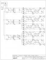
Hope John doesn't mind, I've attached his bulk supply schematic from an earlier post. (if you don't have it)
Gary
Attachments
Hi Studiostevus,
I'm presently using John's MODPWR2 "bulk supply" before the Salas shunt regulators. These have a tremendous impact on the level of detail, the midrange is awesome! The ripple reduction circuit does a great job of bringing down the noise to virtually nothing which I believe is contributing to what I am now hearing. One think I did not use is Schottky diodes; just sticking with regular 1N4007 diodes and added a tuned RC snubber on each diode.
I'm presently doing my PCB with the Salas Shunts on the same PCB as the TDA1541A S2 (I can do quick proto PCB's in my shop which are pretty good). Will it be a bit bigger? Yes...worth it? yes. I'm using the Salas in a couple of other parts of my system - in my preamp, and as the first stage driver regulator on the power amp - can't live without them. Is John's new regulator better? Possibly (and I may try it) but right now I'm sticking with what has worked well and sounds great.
Hope John doesn't mind, I've attached his bulk supply schematic from an earlier post. (if you don't have it)
Gary
Hey Gary,
Interesting, we are on the same path. I actually did the layout for a board with Salas shunts next to the TDA as well. I never got to producing the board, as John then published the Common-mode regulators you attached to your post.
Have you tried to power the TDA directly from the MODPWR2 (so without the Salas shunts) ? How did that sound?
The problem I see is that the Salas shunts are very big, and need adequate heatsinking. In my setup, I am currently using 9 Salas shunts (3 for TDA, 1 for Reclocker, 2 for output stage, and 2 for squeezebox), and of course that gets impossible to build into any casing. Hence the search for more compact (and at least equally good) regulation.
studiostevus,
We are indeed on the same road 😉
I think the MODPWR2 is a "bulk supply", meant as a super-clean pre-filter for the regulators. The voltage out of them is just the right overhead for the Salas shunt input, for the TDA1541A might be a bit high! 😱
Before I was using a CRC filter (4700uF caps) and there's no way that sounds anywhere like the MODPWR2, using that ahead of the Salas shunts is a whole new level! Highly recommended!
For the DAC only, I decided that 3 Salas shunt regulators were adequate. For the reclocking, I thought why not a well designed standard regulated but low noise supply? Less room, less headache. Also, for the on board shunts, I'm using TO-220 FETs which can use a smaller heatsink (in lieu of the plastic pack IRF240/9240 types)
To save room on the reclocking, DAC bulk and CTL PCB's, using surface mount where possible and through hole audio grade parts in any signal paths.
I opted out for an SRPP stage using Siemens CCA tubes, the sound surpasses anything else I tried. I managed to tweak the circuit to get the 2nd harmonic down to -93dB. Totally happy with it! For I/V, I'm using a Takman 2W (100 ohm) in parallel with a Mills MRA5 (120 ohm) giving me about 54 ohms, perfect with the tube stage, smooth sound and great dynamics. I'm still at a bit of a loss to understand the argument against using an I/V resistor, combined with a properly designed tube stage it's great. At least running through my pair of Class A tube amps it sure sounds great!
So I end up with these 6 PCB's:
1A - DAC Bulk power supply PCB
1B - TDA1541A PCB with regulators and I/V, includes DC nulling at DAC output
2A - Control PCB with PIC, USB & SPDIF inputs (PCM2707), switching w/ CS8416
2B - Reclocking PCB with DEM
3 - Tube Stage PCB
4 - Salas SSHV PCB for tube stage
The CTL and Reclock PCBs (2A,2B) have the same footprint and will stack to save room. Ditto for the bulk supply and TDA1541 PCB (1A,1B), those will have a single sided (blank) copper PCB between them for RF and noise isolation. That effectively makes just 3 footprint areas for the PCB's in the chassis, a little easier to manage! I also had a custom transformer made by Hammond (in Ontario Canada) with 6 separate windings and a Flux shield for RF isolation.
Right now the PCBs is sitting on a wood board as I'm still doing some tweaking and not quite done the CTL and reclock PCB layout yet. For clocking right now, I'm using a Teradak USB to I2S for recovery, and into the TDA1541 (except for buffering resistors) However, I am doing the DEM reclocking using BCLK into a 74HC02 and buffering resistors. Even with this setup, the sound is unbelievable, superior now as compared to my "modded" Jolida JD100 CD player.
Like you, having fun...and that's what really counts! And learning a lot from everyone on this thread in the last 2 years, especially John, whose generous contributions have been informative, inspiring and turned me into a total TDA1541A junkie looking for another fix 🙂
Gary, very elaborate reply.
You're right, the MODPWR2 is a pre-supply as far as I understand. John suggested earlier to combine it with the post regulators in post #4008. Have you tried any of this instead of the Salas shunts?
Aside from size, the Salas shunts need significant heatsinking. I recall it is recommended to have at least 100mA additional on the CCS on each reg. I think John has tested Salas shunt as well, but never adopted them (not sure why)...
I am using a discrete output, which sounded much nicer than the Lampizator style output I also tried. It's very nice, but I am also preparing a Gomes output stage as advertised by Thorsten Loesch (want to see if it's as good as he claims 🙂).
For input, I replaced the Teralink X2 with Sqeezebox input (straight i2s). That was a great step up in sound and user experience...!
Gary, very elaborate reply.
You're right, the MODPWR2 is a pre-supply as far as I understand. John suggested earlier to combine it with the post regulators in post #4008. Have you tried any of this instead of the Salas shunts?
Depending on the complexity of his new regulators I may (or may not) try them. However, I'm unlikely to change at this point as I've pretty much bought into the Salas regulators (I have the parts already too!)
Aside from size, the Salas shunts need significant heatsinking. I recall it is recommended to have at least 100mA additional on the CCS on each reg. I think John has tested Salas shunt as well, but never adopted them (not sure why)...
The power dissipation is a negative on the regulator; but in the end the positives outweigh that, and I've made way on the board to accommodate
the heatsinks as needed...
Gary
Hi studiostevus,
Both my brother and I are now working on the new SD-player with built-in DAC and stepped shunt volume control.
Hi John, I am wondering whether there are any updates from your side…
Both my brother and I are now working on the new SD-player with built-in DAC and stepped shunt volume control.
The mystery of lost bits solved
Bernard raises a 'killing concern' and dismisses the TDA1541 altogether. But he may be jumping to conclusions, his argument looks like the technical rebuffing of the TDA1540 (that concatenated the bits from 16 to 14).
So what do I think the real reason for the off-measurements are?
In an article in L'Audiophile no. 13 (nouvelle série), Déc. 1990 Jean Hiraga writes about low signals with as general conclusion that it is clear that multibits gives the best outcome, but analogue even is better. There are many steps affectionados have to take to make great implementations, he mentions, like power supplies and earthing.
Have a look:

A revealing picture.
It shows the effect of stock ceramic capacitors on the signal, and how the performance of the chip can be with audiophile caps. Yes, stock is is bland and noisy, but with audiophile caps of 220 nF there is a clean signal. Very revealing.
It underscores the importance of good caps, and John has taken the utmost in finding good caps with a short signal path and low inductance.
For me the TDA1541 and TDA1543 are chips that sound lifelike and analogue, and 'tube-like' even if the latter is sometimes somewhat raw. They sound warm and I can pull up the volume.
albert
1) A simple test: 1 khz -60dB or - 80dB dithered sine wave displayed on a spectrum analyzer without averaging will show the noise floor. Comparison with other DACs will reveal the truth.
Bernard raises a 'killing concern'
and dismisses the TDA1541 altogether. But he may be jumping to conclusions, his argument looks like the technical rebuffing of the TDA1540 (that concatenated the bits from 16 to 14). So what do I think the real reason for the off-measurements are?
In an article in L'Audiophile no. 13 (nouvelle série), Déc. 1990 Jean Hiraga writes about low signals with as general conclusion that it is clear that multibits gives the best outcome, but analogue even is better. There are many steps affectionados have to take to make great implementations, he mentions, like power supplies and earthing.
Have a look:
A revealing picture.
It shows the effect of stock ceramic capacitors on the signal, and how the performance of the chip can be with audiophile caps. Yes, stock is is bland and noisy, but with audiophile caps of 220 nF there is a clean signal. Very revealing.
It underscores the importance of good caps, and John has taken the utmost in finding good caps with a short signal path and low inductance.
For me the TDA1541 and TDA1543 are chips that sound lifelike and analogue, and 'tube-like' even if the latter is sometimes somewhat raw. They sound warm and I can pull up the volume.
albert

Hi studiostevus,
Both my brother and I are now working on the new SD-player with built-in DAC and stepped shunt volume control.
Could you post some more info and schematics of the MK8 PSU?
Dear John,
You convinced me to build your outstanding TDA1543 DAC with some modifications:
use alkaline batteries as PSU 4X1.5v D cell in series direct supply to the +5V (it will be +6V but 1543 should survive)
Tap in the middle of the 4x1.5V series to obtain the 3V that goes to the I/V resistors. Or has it to be 3.2V exactly? maybe by changing the value of the I/V resistors (820R) it is possible to have 3.0V as the best bias reference?
Any advice on this?
Depending on the complexity of his new regulators I may (or may not) try them. However, I'm unlikely to change at this point as I've pretty much bought into the Salas regulators (I have the parts already too!)
The power dissipation is a negative on the regulator; but in the end the positives outweigh that, and I've made way on the board to accommodate
the heatsinks as needed...
Gary
Roger, did you need to put any heatsinks on the MODPWR2 ?
Last edited:
Roger, did you need to put any heatsinks on the MODPWR2 ?
Hi,
I used the small clip-on heatsinks, they proved adequate for the power dissipation. This may not be case for you studiostevus if your transformer secondaries are different from what I am using.
Regards,
Gary
Roger, did you need to put any heatsinks on the MODPWR2 ?
Here's a link to what I used:
Digi-Key - 345-1087-ND (Manufacturer - 274-2AB)
Gary
Hi triode_al,
That's bernhard's personal opinion.
I rely on facts like Philips datasheet specs and publications that specify Edl of typical 0.5 LSB and MSB change glitch of 0.25 LSB for TDA1541A. These were carried out using a decent lab measurement setup. Poor TDA1541A application and / or measurement setup can lead to different measurement results and that's probably what happened here.
We talk about LSBs and 16 ... 24 bit resolution and how important it is to gete every last bit.
Imagine we visualize bit resolution by translating DAC full-scale output signal to say a distance of 10 kilometer or 1,000,000cm. Then a LSB change on a 16 bit system would represent 1,000,000 / 65,536 = 15cm on a distance of 10 kilometer.
For a 24 bit system a LSB change would represent 1,000,000 / 2^24 = 590 micrometer or 0.059cm on a total distance of 10 kilometer.
With these high to extreme resolutions, the limits of audio equipment will be the dominating factor, not DAC bit resolution.
Indeed, it shows two examples of ineffective active divider decoupling.
Bernard raises a 'killing concern' and dismisses the TDA1541 altogether.
That's bernhard's personal opinion.
I rely on facts like Philips datasheet specs and publications that specify Edl of typical 0.5 LSB and MSB change glitch of 0.25 LSB for TDA1541A. These were carried out using a decent lab measurement setup. Poor TDA1541A application and / or measurement setup can lead to different measurement results and that's probably what happened here.
We talk about LSBs and 16 ... 24 bit resolution and how important it is to gete every last bit.
Imagine we visualize bit resolution by translating DAC full-scale output signal to say a distance of 10 kilometer or 1,000,000cm. Then a LSB change on a 16 bit system would represent 1,000,000 / 65,536 = 15cm on a distance of 10 kilometer.
For a 24 bit system a LSB change would represent 1,000,000 / 2^24 = 590 micrometer or 0.059cm on a total distance of 10 kilometer.
With these high to extreme resolutions, the limits of audio equipment will be the dominating factor, not DAC bit resolution.
Have a look: TDA1541 lot bits.jpg A revealing picture.
Indeed, it shows two examples of ineffective active divider decoupling.
Gary, just wondering... how and if have you implemented the circuit on the primary side? Are you using thermistors?
- Home
- Source & Line
- Digital Line Level
- Building the ultimate NOS DAC using TDA1541A