It´s possible to do a lot better (measurement and soundwise) by using one TDA1543 per channel, using only the right channel of the chips, and by selecting chips for low MSB error. I have found this a necessity when I ditched the volume control (started using digital volume). Particularly when I listened late at night with absolute silence outside the flaws became very audible.
The manufacturer´s comment on the next page makes no sense to someone who understands what is going on. He says that R-2R dacs are superior in accuracy; well, NOT the tda1543! First of all, it is not even R-2R. It is pretty inaccurate.
But we have to make the distinction: objective vs. subjective. My criticism is the marketing BS and trying to imply an "objective rightness" where there is little of that.
The tda1543 passive sound (relaxed and soft) is more because of flaws and inaccuracies. I still like it, even knowing this. Somehow the psychoacoustic effect works and you may perceive it as sounding right. To me it is reminiscent of cassete tape sound. But again, there is little technical rightness to it. I like having other options.
Abraxalito mentioned that you have extensive knowledge relating to the TDA1543, and so I found a post of yours from some time ago. My experience with this chip is like yours, that it was relaxed and soft (with limited detail). This was somewhat expected for the reasons you describe.
My question relates to the reason for subjective limitations. Do you have any experience with I/V converters being attached to the TDA1543 with a more or less fixed input voltage and an input impedance perhaps below 10 Ohm's? I am wondering if subjective limitations exist in part for the reasons that many implementations fall far outside the +/- 25mV AC compliance limitations of the TDA1543.
It is considered that die sizes were much larger back then, whereupon dielectric constants of capacitances generating the bits could have greater influences in softness and masking. By terminating the motion with a low value load impedance of an I/V the influence of dielectrics would diminish, simply because they are no longer moving. This seems as the only chance the TDA1543 has in todays marketplace of alternative DAC's.
Also: Is there a kit with a BOM and is this something a green builder could put together?
The answer to the first part is 'yes' - see my recent update in post #1 : lingDAC - cost effective RBCD multibit DAC design
As for the last part - I hope so but if you're new to SMT you might want to practice soldering a bit first as most of the parts (resistors, caps) are 0805 footprint which is 2mm long by 1.2mm. ICs are 1.27mm pitch so nothing very fine but compared to TH (through hole), half the pitch.
The answer to the first part is 'yes' - see my recent update in post #1
As for the last part - I hope so but if you're new to SMT you might want to practice soldering a bit first....
Nice!
That'll give me at least some time to practice smd-soldering, which is something that I dearly need... Sounds like a superinteresting project! Is there an estimate what the pcb's will cost and maybe a complete build as well?
Thanks for the answer!
/Hilding
Very glad to hear you find it so interesting.
PCBs - you can order those yourself when I publish the gerber file set. That's generally the cheapest way to get them - direct from the factory PCBs are almost unbelievably cheap nowadays and factories get good deals on shipping rates. Of course you can also get PCBs from me as part of a kit.
As for the complete cost I've not yet calculated it as there's a substantial labour element (my time) involved. I hope it will be under $100 (USD) for a kit. The kit will include the LC filter as a ready-built item and that's where most of the labour time is spent. The customer can choose between the two filters I've shown characteristics of in recent posts in this thread. The single inductor filter is quicker to build hence will be considerably cheaper.
Here's a shot of the first completed prototype PhiDAC hex r1 which played music first time on switch on 🙂 I changed the colour of the nylon bolts through the inductor cores to closer match the sleeves of the 'lytics. What do you reckon - is black better than off-white?
Attachments
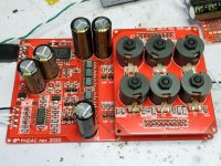
Here's a shot of the first completed prototype PhiDAC hex r1 which played music first time on switch on 🙂 I changed the colour of the nylon bolts through the inductor cores to closer match the sleeves of the 'lytics. What do you reckon - is black better than off-white?
The whole thing looks great. Black is better against the inductor core, creating an integral solid block look about the inductors themselves, as thereupon the whole of this board is more substantial looking. Otherwise, the dark inductors against the off-white nylon bolts creates a confused busy look generating an off-putting tension in the subconscious. Though one could ask "What does better mean?"
This version looks serious. The size of the inductors make it look like it means business. That is of course psychobabble but, it does look impressive. The real question is, how does it sound compared to the origial Lingdac and the the origial Phidac?
Have you experimented with adding extra DAC chips to your PhiDACs @pelopidas? You'll be able to get a flavour of how much improvement in the noise floor more chips brings.
Here's a shot of the first completed prototype PhiDAC hex r1 which played music first time on switch on 🙂 I changed the colour of the nylon bolts through the inductor cores to closer match the sleeves of the 'lytics. What do you reckon - is black better than off-white?
White is ok, but black does match the inductors better 🙂
Have you experimented with adding extra DAC chips to your PhiDACs @pelopidas? You'll be able to get a flavour of how much improvement in the noise floor more chips brings.
I have the board mostly ready. Just waiting on the new resistors and capacitors from Mouser. Should hopefully arrive beginning of next week.
^^Naa, tja! It goes in a case.
Yes, but if colours are nicely matched it plays better 😉
True! Matching colors and symmetrical layout is -3db reduction in noise and +2 in dynamic range 😉
I've turned my 2nd prototype PhiDAC hex into a 'DodecaDAC' - couldn't resist soldering on an extra layer of chips to get 12. The DAC chips need a reduction in supply voltage to achieve this result as there's otherwise more current than the I/V stage can reasonably handle. I've gone down to 2.35V supply for the TDA1387s and haven't noticed any SQ degradation nor measured any significant increase in distortion as a result of running the chips below their minimum.
Of course this is all just a distraction from getting the BOM finished....
Of course this is all just a distraction from getting the BOM finished....
And what did this do to the sound? 😉 by the way, I thought you mentioned in this thread that you will offer this as a kit (set of boards with components). Can you confirm if this is still your plan?
Too soon to say how, if at all, 12 chips is better than 6. It needs quite a bit of listening to tease out any way the SQ has changed. Initially I haven't noticed any difference.
Yes, still the plan to offer the DAC design as a kit next month.
Yes, still the plan to offer the DAC design as a kit next month.
Great! I'll be checking in here regularly. I look forward to compare this with my quite more expensive dddac. One good thing of the otherwise dreadfull C19 crisis, is that it enables me to build and listen to music more than ever. Stay safe and enjoy our mutual hobby!
There are always upsides to any downside - for example the people in India who can see the Himalayas for the first time due to the huge reduction in pollution.
If not for the virus I'd be still focussing on my transformer-based DAC design and getting kits out for that so this particular project wouldn't be in existence.
If not for the virus I'd be still focussing on my transformer-based DAC design and getting kits out for that so this particular project wouldn't be in existence.
Hey Abraxalito, quick question.
The resistors and capacitors for the quad version will arrive in a few days. I have a single dac chip soldered onto the board right now. When the other resistors and capacitors get placed on the board, I wanted to power it up and check that it all works before adding the other dac chips. Is there a way to measure each chip as I go for function? Should I just solder it ontop, leaving pin 6 floating and measure that one for voltage? What is the best approach?
The resistors and capacitors for the quad version will arrive in a few days. I have a single dac chip soldered onto the board right now. When the other resistors and capacitors get placed on the board, I wanted to power it up and check that it all works before adding the other dac chips. Is there a way to measure each chip as I go for function? Should I just solder it ontop, leaving pin 6 floating and measure that one for voltage? What is the best approach?
- Home
- Source & Line
- Digital Line Level
- lingDAC - cost effective RBCD multibit DAC design