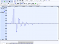
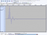
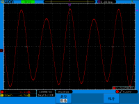
I made some measurements with two different analog filters in my DAC, stimulated by artificially created impulses. Based on the impulse responses, which sounds better?
There must be a catch 😉
I would say the one on the second photo just by looking at the response... But I have a feeling that it is the first one?
Did you try it only by yourself or...?
Of course there's going to be a catch or no fun!
The two are the ones me and my wife compared a few posts back (one is the 1 inductor filter, the other is the 3 inductors one), I'm not saying which is which just yet but anyone with a modicum of knowledge about filters will be able to identify them from their impulse responses.
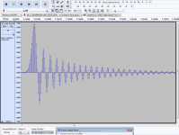
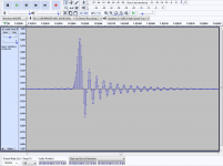
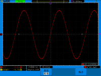
I've since made a recording of what happens when we run 2XOS with SoX providing the upsampling to 88k2. Compare this one (which has a digital filter as well as an analog one) with the two above, which are just analog filters (hence NOS).
The two are the ones me and my wife compared a few posts back (one is the 1 inductor filter, the other is the 3 inductors one), I'm not saying which is which just yet but anyone with a modicum of knowledge about filters will be able to identify them from their impulse responses.
I've since made a recording of what happens when we run 2XOS with SoX providing the upsampling to 88k2. Compare this one (which has a digital filter as well as an analog one) with the two above, which are just analog filters (hence NOS).
Attachments
Last edited:
... It is in result of my contribution, while not acknowledged by a project leader, it cannot be denied......l]
Your repeated references to your contribution reflect poorly on your person. This is a forum... it's all about contribution. What do you want? A medal? Stop doing it, you are making a fool out of yourself.
//
I made some measurements with two different analog filters in my DAC, stimulated by artificially created impulses. Based on the impulse responses, which sounds better?
OK... for the fun of it... I like the one on the left, being the one that looks closer to instability, as trying to hog all the energy into some peak resonance and leaving nothing for the others. From this questionable perspective the one on the left sounds more laid back with an ability to capture more detail, micro dynamics and three dimensional space.
Couple of questions, very good and you know answers. Just to add to the beginning that human brain works like a fine DSP filter. In fact we have already learned that hear sensors generate not analog signals, but pulses. We re able to pickup individual samples from thousands of hear sensors and fill-up missing information. BTW, there is no missing information according to Nyquist, but I still use this term having no better. This 'missing' information is processed in our brain with greater precision than any DSP engine can do, without any side effects of current DSP technology. In other words our hearing do not suffer from processing 'steps'.I am currently running a NOS TDA1541a DAC (inside an inherited Naim CD3). This is connected to a non-feedback I/V design capable of operating at input currents above +/- 10mA. This also has a uniform input impedance of around 3 Ohms into the MHz region. The 3dB rolloff of the I/V was limited to 1.5 MHz from around 5MHz for reasons that my tube preamplifier began reminding me of Sparky. [...]
To engage in reproducing all frequencies into the MHz region is not recommended as a finished product. Yet to do so can clarify an understanding of variant factors in the reproduction. Particularly in gaining incite into the degree linearity and filtering that is necessary. This is to suggest that if the audio reproduction is formidable with a 6dB/pole located at 1.5MHz, what benefit exists in removing the visible signs of the steps. What added value is expected using a brick wall filter or perhaps 2XOS? Filtering can obscure better performance.
Now, if we are trying to help our brain with inferior technology, we are filling up missing information with rubbish. A sound is compared in our brain with natural templates in order to reduce processing time and a rubish is forcing brain to reject templates, leading to fatigue over extended listening sessions. NOS DAC with a simple analog filter do not cause fatigue. It is the best proof of the concept.
Yip this is a concern. IMD distortions on the I/V converter of high frequency tones create products in the audio range. It is also true in the entire channel: a DAC output stage, amplifier, speakers and finally in our ears. For this reason @abraxalito's solution is a filter before I/V conversion. Another slow roll-off filter should be after I/V conversion. A sanity check is needed and weight of advantages and negative aspects should apply.One question comes to mind: How faithfully can an I/V converter reproduce a step function waveform before filtering is applied?
There is no place for a brick wall filter in my R2R DAC. Another question is regarding 2x/4x OS with a slow roll-off filter, I haven't investigated it more yet.
Last edited:
My contribution has been denied repeatedly, the only reason. We are not fools as some may think.Your repeated references to your contribution reflect poorly on your person. This is a forum... it's all about contribution.
One question comes to mind: How faithfully can an I/V converter reproduce a step function waveform before filtering is applied?
There's an interesting paper on this by Hawksford which can be downloaded from Researchgate : (PDF) CURRENT-STEERING TRANSIMPEDANCE AMPLIFIERS FOR HIGH-RESOLUTION DIGITAL-TO-ANALOGUE CONVERTERS
From my own point of view, as @sajunky has pointed out, I use a filter between Iout DAC and I/V converter. This means there's no step function applied to the I/V - all the I/V sees is a continuous waveform as the steps have been removed by the filter. Putting a filter there has a significant downside - noise. But subjectively the upside is a more 3D presentation, a much more enjoyable sound so I consider the noise price worth paying, at least on a 16bit DAC. Those who wish to use a filter on higher bit-depth DACs will have bigger noise issues than for RBCD.
Incidentally, thanks for the 'feedback' on the filters. Anyone else willing to have a guess?
I'll bite. Impulse on the left is the single inductor filter, and on the right is the triple inductor filter. I feel pretty sure that you like the sound of the steeper filter best--since your experiments have led in that direction for a while 🙂
Can we also play this game with some 18KHz sine waves?
Can we also play this game with some 18KHz sine waves?
So your guess is I prefer the one on the right, the one which has less ringing?
What's the game with the 18kHz sinewaves? You want to see if it has any 'steps' on it?
What's the game with the 18kHz sinewaves? You want to see if it has any 'steps' on it?
LOL, mixed up my left and right there. I'll try again...I think the one on the left, with more ringing, is the steeper triple inductor filter and your favorite-sounding.
I would like to see if there is a visible difference between the filters with a sine wave.
I would like to see if there is a visible difference between the filters with a sine wave.
Yep, you're right on the money. The steeper filter has more ringing and sounds better than the shallower one with less ringing. Which is the 'catch' so perceptively identified by @bozoc.
I'll do those 18kHz sinewave captures in a short while. Yes there's definitely a difference, based on when I've done this with earlier incarnations of my DACs.
I'll do those 18kHz sinewave captures in a short while. Yes there's definitely a difference, based on when I've done this with earlier incarnations of my DACs.
Interesting. ThanksJust to add to the beginning that human brain works like a fine DSP filter. In fact we have already learned that hear sensors generate not analog signals, but pulses. We re able to pickup individual samples from thousands of hear sensors and fill-up missing information. BTW, there is no missing information according to Nyquist, but I still use this term having no better. This 'missing' information is processed in our brain with greater precision than any DSP engine can do, without any side effects of current DSP technology. In other words our hearing do not suffer from processing 'steps'.
Now, if we are trying to help our brain with inferior technology, we are filling up missing information with rubbish. A sound is compared in our brain with natural templates in order to reduce processing time and a rubish is forcing brain to reject templates, leading to fatigue over extended listening sessions. NOS DAC with a simple analog filter do not cause fatigue. It is the best proof of the concept.
Hawksfords' paper covers theoretical material that mirrors what I am finding and addressing. Mine is also a transimpedance design. By the way, aren't all transimpedance amplifiers somehow current steering? Excellent paper though. Thanks.There's an interesting paper on this by Hawksford which can be downloaded from Researchgate : (PDF) CURRENT-STEERING TRANSIMPEDANCE AMPLIFIERS FOR HIGH-RESOLUTION DIGITAL-TO-ANALOGUE CONVERTERS
This makes sense. However, it is questioned if the filter you are using between your Iout DAC and I/V converter is universally applicable. In particular there is a distinct difference between the TDA1541a and the TDA1387, in that the voltage compliance of the former is +/-25mV and yours is +3V to ground. The question is: What is the magnitude of voltage at the input of your filter with full scale DAC current applied and the other end of the filter grounded (the I/V input end)? It seems unlikely that the voltage would be limited to +/- 25mV as to remain in compliance with the TDA1541a's spec's. Given a full-scale output of 2.5mA requires no greater than 10 Ohm as seen by the DAC in order to remain within that boundary.From my own point of view, as @sajunky has pointed out, I use a filter between Iout DAC and I/V converter. This means there's no step function applied to the I/V - all the I/V sees is a continuous waveform as the steps have been removed by the filter. Putting a filter there has a significant downside - noise. But subjectively the upside is a more 3D presentation, a much more enjoyable sound so I consider the noise price worth paying, at least on a 16bit DAC. Those who wish to use a filter on higher bit-depth DACs will have bigger noise issues than for RBCD.
No doubt the TDA1387 is far superior as being closer to a true current source, and thereupon not nearly as reliant in seeing a zero resistance load as the TDA1541a. The TDA1543 also has an AC voltage compliance of +/- 25mV. Many implementations of the TDA1543 seems going far outside their compliance range, hence it is questioned as to the reliability of listening tests evaluating such devices under such circumstances. This is not to suggest that going outside the voltage compliance boundaries, notwithstanding how far, doesn't have significant sonic advantages, yet to assert that the TDA1543 is itself superior or inferior to devices like the TDA1387 isn't necessarily justifiable under such circumstances. The point being is that I am left wondering if the TDA1543 isn't yet some form of sleeping giant, however insignificant it might seem to be in relation to newer and truer current sources like the TDA1387.
I am also experiencing more noise with my implementation of the I/V. This is without input filtering. Effectively I am in the same boat as you, though considering trading off more noise for the kind of possible upside as you mentioned.
This makes sense. However, it is questioned if the filter you are using between your Iout DAC and I/V converter is universally applicable.
Its not universally applicable, no. It can be applied to all current source output DACs though I believe, with circuit modifications.
In particular there is a distinct difference between the TDA1541a and the TDA1387, in that the voltage compliance of the former is +/-25mV and yours is +3V to ground.
Excellent point - though its 3.5V to GND on a 5V supply.
There are considerable variations in how output compliance is specified for DACs. TDA1543 is most explicit in that it gives both a DC and an AC output compliance. TDA1541A just puts the compliance in a footnote but doesn't say what performance losses will accrue if the 25mV is violated. TDA1387 gives a very wide range and doesn't hint that there's any difference between AC and DC.
Many years ago when Thorsten Loesch was active here I recall him saying (though my memory is hazy) that the 25mV for TDA1541A wasn't a hard and fast limit in his experience, that it could be exceeded in practice. By how much though he was a bit cagey, guess he considered that his IP. I got the impression that even 50mV was probably OK in practice. I don't recall seeing anyone using an I/V resistor as low as 12.5ohm in DIY DACs but I spend very little time hanging out in TDA1541A discussion threads so I'm far from being an authority on such matters.
The question is: What is the magnitude of voltage at the input of your filter with full scale DAC current applied and the other end of the filter grounded (the I/V input end)?
That's something I have paid attention to in simulation, its a function of frequency to some extent - as the filter corner frequency is approached the voltage gets higher by 6dB or so from the low frequency case. (The effect is even more pronounced when a transformer's used, so an RC snubber is applied to keep the HF excursions under control). I generally aim for keeping less than 200mV peak excursion at LF. Its a trade-off between that and noise from the I/V.
It seems unlikely that the voltage would be limited to +/- 25mV as to remain in compliance with the TDA1541a's spec's.
With the current filter design, you're quite correct. But it can be adapted to give lower excursion - 25mV though would be quite a challenge for the I/V stage's noise. Many paralleled stages of AD829 would work though I think. Capacitor values in the filter would get to the region of 1-3uF which is a bit expensive if they're kept as C0G/NP0. Inductor values become more coarsely quantized which presents another challenge - the filter though could be split into multiple stages to get around this.
No doubt the TDA1387 is far superior as being closer to a true current source, and thereupon not nearly as reliant in seeing a zero resistance load as the TDA1541a.
TDA1387 is indeed a very high impedance current source output. I don't know enough about TDA1541A to comment.
The TDA1543 also has an AC voltage compliance of +/- 25mV. Many implementations of the TDA1543 seems going far outside their compliance range, hence it is questioned as to the reliability of listening tests evaluating such devices under such circumstances. This is not to suggest that going outside the voltage compliance boundaries, notwithstanding how far, doesn't have significant sonic advantages, yet to assert that the TDA1543 is itself superior or inferior to devices like the TDA1387 isn't necessarily justifiable under such circumstances. The point being is that I am left wondering if the TDA1543 isn't yet some form of sleeping giant, however insignificant it might seem to be in relation to newer and truer current sources like the TDA1387.
Have a chat with @Alexandre - he's got a wealth of knowledge to share about TDA1543. To me it sounds softer than TDA1387, rather like film as opposed to video or cassette as opposed to CD.
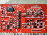
New PCBs arrived
First rev1 prototype taking shape...
I do this in a couple of stages so as to minimize the potential losses should something go wrong. The power supply circuits are the first to be powered up but they're not initially connected to the opamps and DACs - ferrite beads in the power rail aren't fitted. Then if there's a serious fault the consequences are limited. Once the power supplies are checked good with a DMM then I'll connect them up to the filter-I/V stages.
Attachments
Late to the party but subscribed!
Also: Is there a kit with a BOM and is this something a green builder could put together?
/Hilding
- Home
- Source & Line
- Digital Line Level
- lingDAC - cost effective RBCD multibit DAC design