Good point, the DC gain of the TL431 isn't as high as 10dB though, in this case about 5dB. So a cap could indeed lower the noise by 5dB.
I wonder though if I fit an X7R the microphony from that might exceed the noise gain? I have put a 100uF 'lytic on as an experiment and didn't notice any improvement in SQ however my wife just pointed out something from her listening so I need to fix that up first then return to this 🙂
Thanks for picking up on this point.
Yes, you are right. As the voltage gain is similar to noise gain the possible noise reduction of TL431 would be lower in your circuit. Foil or lytic should be used.
Credits to Poul Petersen.
Credits to Poul Petersen.
A foil cap will be added to the TL431 across R25. I'll increase the R values so that the cap doesn't need to be so big.
My wife's listening threw a small spanner in the works so I thought at first. But her criticism of how notes didn't seem to hang together right made me fire up my 'scope to look at whether the level shifting circuits were doing their job as expected. And it turned out they weren't - the positive going edges of the clock waveform de-biassed the CCSs for an instant which led to a not-so-pretty looking rising edge. So I've increased the CCS bias slightly and bypassed the zeners with small caps. After I executed this mod wifey was more than content with the SQ 🙂
Updated schematic to follow shortly.
I have started soldering 2 Phidac PCBs as described in step 1 of post lingDAC - cost effective RBCD multibit DAC design
After supplying of 12.5V power to the PCB the LEDs D1-D3 light up bright and burned after few seconds. I have replaced them and reduced supply to 5.4V when powering first time. The LEDs bright normal. Raising supply to 6.5V makes the LEDs shine bright and I fear they will burn again if supply is changed to 12V or more.
I have measured in circuit:
R4 = 220
R5 = 81K4
R9 = 42K9
R12 = 982R
R10 = 477R
BC856B Transistors are marked 3B
With 5.4 V suppy (instead of 12V) the testpoints measures as follows:
TP1: 5.23/5.24
TP2: 4.51/4.50
TP3: 4.0/4.0
TP4: 2.22/2.25
TP5: 2.12/2.49
Does anyone have an idea what could be wrong?
My best guess at this stage is you've soldered D4 in backwards. Its not very easy to identify the cathode band on the package, it needs tilting into the light to bring out the contrast.
My best guess at this stage is you've soldered D4 in backwards. Its not very easy to identify the cathode band on the package, it needs tilting into the light to bring out the contrast.
🙄 On one PCB the D4 orientation was wrong, Thanks. The voltages on test points are in valid range now.
The other PCB had 2,69V (instead 2.5V) on TP5. Somehow I managed to kill the CJ431, TP5 measured 10,1 Volts. I have replaced the CJ431 already but get same voltage. I guess the 74HC86D has shortage because of 10V supply and needs to be replaced first. Thanks a lot for supplying spares of mostly all parts!
I have amended the first post on the commercial thread to indicate PhiDeca DAC kit availability : PhiDAC hex kits with pre-built filters
Any technical questions about PhiDeca DAC, please ask on this thread.
@1543 - eagerly looking forward to hearing how the 'hex' sounds vs your earlier NOS DAC builds.
Any technical questions about PhiDeca DAC, please ask on this thread.
@1543 - eagerly looking forward to hearing how the 'hex' sounds vs your earlier NOS DAC builds.
Have you read abraxalito interview? also he has a blog here on diyAudio in the blogs section.
An Interview With Experienced Digital and Analog Designer Richard Dudley – Fair Hedon
An Interview With Experienced Digital and Analog Designer Richard Dudley – Fair Hedon
Ha - have you been looking at my Hackaday page by any chance?
The active speaker project I abandoned quite a few years ago - the idea there was to rip-out the usual chip-amps and replace them with TDA8932 modules but I found the layout and routing of wires was too critical with those cheapo modules. It was much too easy to get the output wires feeding back RF to the input. So eventually I got around to designing my TDA8932 amp board where the input transformer solves that nasty issue - then the trouble is the trafo makes rather a bulky board to retrofit inside an active speaker case. Eventually I will work again on active speaker modifications I think, but it'll be with an external amp-psu-XO box rather than putting all that stuff inside the cabinet.
The active speaker project I abandoned quite a few years ago - the idea there was to rip-out the usual chip-amps and replace them with TDA8932 modules but I found the layout and routing of wires was too critical with those cheapo modules. It was much too easy to get the output wires feeding back RF to the input. So eventually I got around to designing my TDA8932 amp board where the input transformer solves that nasty issue - then the trouble is the trafo makes rather a bulky board to retrofit inside an active speaker case. Eventually I will work again on active speaker modifications I think, but it'll be with an external amp-psu-XO box rather than putting all that stuff inside the cabinet.

Just this week I came across an improved version of the SD card player I'd used in the past (before it became too unreliable) so was keen to snatch one up and have a play.
Its using a much faster CPU (STM32H750) which has enough on-board RAM not to need an external RAM chip. I figure the lack of those high speed external buses should mean lower noise, perhaps lower power too.
YJ-SD ??????????? ??32Bit 192K ???-???
Its using a much faster CPU (STM32H750) which has enough on-board RAM not to need an external RAM chip. I figure the lack of those high speed external buses should mean lower noise, perhaps lower power too.
YJ-SD ??????????? ??32Bit 192K ???-???
Was your older player one of the yellow boards based on STM32F407ZET6?
These players seem like they could offer a very clean source of I2S.
For the newer STM32H750 player, I found in a seller's description:
"only 32GB memory cards are supported." That would be hard to get along with.
These players seem like they could offer a very clean source of I2S.
For the newer STM32H750 player, I found in a seller's description:
"only 32GB memory cards are supported." That would be hard to get along with.
Nice find, glad to see this new version is on aliexpress too.
The yellow version is certainly is a low noise/interference I2S source, but low jitter I'm so not sure (compared to good XMOS interfaces), it's the perfect match for a FIFO buffer.
The new version's MCU has a dedicated oscillator now and audio clock frequency is doubled to 45/49MHz, the yellow version's MCU ran just off the 22/24Mhz audio rate oscillators depending on what was playing.
49MHz oscillator for 48x sample rates is higher than the MCU's max MCU clock speed of 48MHz, which might be the main reason for the dedicated clock. I hope it would bring some other benefits.
Hi To all.
I finally had the time and built the Hex Phidac wich I received some months ago.
Test points are within the specification. Altouhg in one chanel DC voltage between out and ground is 12mv. on the other chanel is 0mv. I replaced C51 capacitor by a normal electrolitic just to test and DC voltage is now very close to 0mv on the afected chanel.
It's worth to replace C39 and C51 by high quality capacitors?
Can they be smaller than 15 uF?
In case they are to big and have to be soldered by wires to the PCB will the sound be afected in any way by the lenght os the wires?
Thanks for your reply.
Was your older player one of the yellow boards based on STM32F407ZET6?
Yes, that's the one.
For the newer STM32H750 player, I found in a seller's description:
"only 32GB memory cards are supported." That would be hard to get along with.
I did catch that detail in the translation of the Taobao page but wasn't sure if it was referring to the type of card needed for a firmware upgrade. I have since checked and the couple of 16G cards I have definitely don't work. Its barely an issue for me as 32G has been the sweet spot for some time (the maximum supported on the earlier player) so almost all of my cards are that.
It's worth to replace C39 and C51 by high quality capacitors?
Yes, that's a worthwhile upgrade to this DAC.
Can they be smaller than 15 uF?
They can - that capacitor is an X5R whose capacitance decreases with increasing voltage across it. So in-circuit its definitely less than 15uF. How low you can go depends on the input impedance of the following circuit. 4.7uF (as used in the Deca DAC) is fairly safe.
In case they are to big and have to be soldered by wires to the PCB will the sound be afected in any way by the lenght os the wires?
I'd keep the wires as short as possible, under 15cm I would doubt there would be any degradation as the output impedance is fairly low (47ohm).
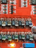
Over on the Bazaar thread @stellarelephant's posts encouraged me to take another look at pin7 capacitors. I looked but could find nothing small enough in polypropylene but I did find some very cute 1uF SMD caps from Panasonic : https://www.mouser.com/ProductDetail/Panasonic/ECP-U1C105MA5?qs=KQ0g6Wi1%252B%252BsinpFL%2FHIsqw%3D%3D
I've soldered up 10 of them (no prizes at all for beauty!) and having a listen. Nothing jumps out so far as having changed...
I've soldered up 10 of them (no prizes at all for beauty!) and having a listen. Nothing jumps out so far as having changed...
Attachments
Yes, that's the one.
I did catch that detail in the translation of the Taobao page but wasn't sure if it was referring to the type of card needed for a firmware upgrade. I have since checked and the couple of 16G cards I have definitely don't work. Its barely an issue for me as 32G has been the sweet spot for some time (the maximum supported on the earlier player) so almost all of my cards are that.
I wonder if something is lost in translation here - but the 32gb thing is puzzling. I have a few of the yellow boards, and they work with cards from 2gb up (haven't gone beyond 32gb). Abraxalito - are you saying they will only work with 32gb, no smaller sizes?
Its says the same on the ads for the yellow boards.
My yellow board isn't functioning these days - the display has gone blank but it still can play music. I've not been talking about that old board, rather the new black one.
Yes my yellow board didn't have problems with smaller cards - certainly it didn't work with >32Gb as that's another interface protocol. It didn't have problems with slower cards either, just sometimes had problems rather randomly with accessing cards and those problems seemed to correlate with card brand name. The new board's blurb does say slow cards won't work (class 4 and class 6).
What I'm saying is the new black board didn't work with the two 16Gb cards I tried (which were class10 I think).
Are you saying that the blurb for the yellow boards now says they won't work with <32Gb? If so then I could only attribute that to a firmware change on the recent offerings as mine definitely did.
- Home
- Source & Line
- Digital Line Level
- lingDAC - cost effective RBCD multibit DAC design