I can try 🙂I won't claim the Pi has super powers when it comes to CPU performance. However, it is more than sufficient for my needs as a streamer or transport for music data. I'd like to understand why anyone would want more. Can you shine some light on this?
First of all, the Hackboard 2 as well as the Oddyssey offers M.2 storage (up to 4TB) and personally, I a huge fan of local storage. Second, its the x64 protocol which is more future prof and better memory utilization.
Third, better IPC (instructions per clock) which reduces latency and lag. Just like higher internet data speed reduced such issues. Fourth. I am planing this build for the next decade and because of that, I want to start with higher spec than the Pi such that by the end of the streamers 10 years, the likelihood of it still having a good amount of CPU headroom is higher than the Pi.
Better headroom is a mantra for PSU design, so why not here. After all, its not a super computer 😉 Software mature, get more complex, demand higher spec, more RAM, more CPU etc. In 2021, I would say that starting on something petter than an Arm A-72 processor is recommended.
There are them who have a music server which is better specked than my Core i7 4770K 32GB memory PC I'm on right now because I can't upgrade, which to me is kinda insane, but that is what they want.
So, my initial post on the "which board to get" was me pointing out that if one like to have a better processor than the A-72 and maintain the RPi GPIO infrastructure, then that board could be the Hackboard 2 - pending release. But if one don't want or feel the need for anything else than the RPi3/4, then all the better.
2 cents
I am trying to find my way through the jungle of Ians power supply options... HELP! 🙂
I am currently running a RPi with a FiFoPi, which feeds a DDDAC. The RPi and FiFoPi are running of the same external power supply, with no local "PSU cleanup" at the RPi/FiFoPi.
I guess I could improve this with one of Ians power supply boards. I need a power supply that continuously supplies the RPi and FiFoPi (no downtime for charging), so I guess batteries are out. Also, I'd prefer a simple HAT like board that goes on the RPi. Finally, it would be nice if the board would also support an additional ReclockPi board stacked onto the FiFoPi.
Which board is right for me?
Where did you get this? [emoji4]View attachment 950823
I destroyed a gpio to i2s header for a raspberry pi. If anyone has a source for conversion pcb’s of U.FL. I am interested 😉
just looking at the photos i reckon you can improve by a lot by properly doing a pcb for the tda...
that chip deserves far better layout 🙂
Yes it does. This is my first attempt for a TDA dac, so please be gentle on me 🥴, however this layout is not too bad, all dem smd capacitors are below the chip attached to a ground plane copper strip.
But you can relax; today my Pcb’s of distinction 3 dac and i2s-simultanous conversion boards have arrived. So next week I can probably report how bad my perfboard is in comparison😉
Hello,
A bit funny Ian told us to wait for the manual and still there are people for who things are not clear.
Maybe Ian should add more photos.
If you connect a DDDAC with 3 UFL cables let them '' leave '' from the added board or the Fifopi board. Just a one photo will show it clearly
Greetings, Eduard
There are also people who read the manual when purchasing a new vacuum cleaner...........
But we techheads throw away the manual and start disassembling the thing right away😀
I am trying to find my way through the jungle of Ians power supply options... HELP! 🙂
I am currently running a RPi with a FiFoPi, which feeds a DDDAC. The RPi and FiFoPi are running of the same external power supply, with no local "PSU cleanup" at the RPi/FiFoPi.
I guess I could improve this with one of Ians power supply boards. I need a power supply that continuously supplies the RPi and FiFoPi (no downtime for charging), so I guess batteries are out. Also, I'd prefer a simple HAT like board that goes on the RPi. Finally, it would be nice if the board would also support an additional ReclockPi board stacked onto the FiFoPi.
Which board is right for me?
If you want a HAT like power supply board, then the ConditionerPi would be your only option.
#30A
GitHub - iancanada/DocumentDownload: Download documents of Ian's products
Ian
thorsten loesch swears by the perf board with copper ground plane. He dissed all the DIY PCB attempts. Personally I think Ryan did a pretty awesome job on V3 with the 4 layer PCB and the I2S attenuation. I still run V1 but one day intend to try V3.Yes it does. This is my first attempt for a TDA dac, so please be gentle on me 🥴, however this layout is not too bad, all dem smd capacitors are below the chip attached to a ground plane copper strip.
But you can relax; today my Pcb’s of distinction 3 dac and i2s-simultanous conversion boards have arrived. So next week I can probably report how bad my perfboard is in comparison😉
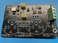
UC Conditioner
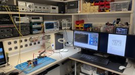
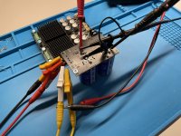
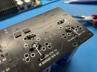
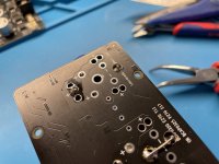
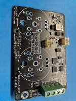
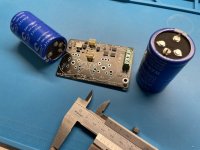
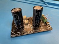
I ordered some stuff from Ian to add to my DDDAC/Andrea clock test setup with the FiFoPi. Also his linearPi with the UC Conditioner boards. I had some Ultracaps from AliExpress lying around. 😱 Pity they did not fit 🙄
So we had to fix this ! see images. speak for them self I guess. Please if doing this be VERY careful, the plus and minus are opposite board sides with one UC cap 😱
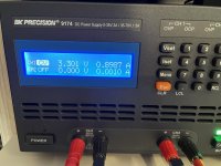
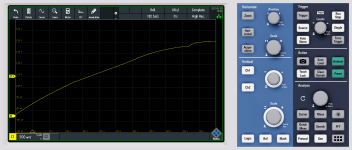
Other pics show the charging of the Ultracaps it self: It takes roughly 10 minutes as you can see and charge current is roughly between 0.5 and 1 Ampere. Slowly getting more and more as voltage rises.
You can also see clearly the jump in the plot at a level of 3.1 Volt: the UltraCap is just switched onto the power supply just like that. This causes a short moment current charge peak. My LAB supply blocked it in CC of course. Most power supplies will be able to deliver a short peak. Unless they have a fuse or electronic shut down. Just saying...
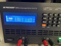
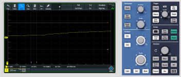
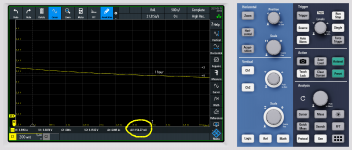
When the UC is switched off, the UltraCap is disconnected and self-discharges - see other picture. in one hour 150mV or so. After 12 hours 2,75V was left. So when switching back like "the next day" or so it probably will be a bit round 2,5 Volts and the charge time will be only 3-4 minutes
just wanted to share this - not sure if the right thread, but hopefully close enough as this Ian Canada's stuff 😎
.
I ordered some stuff from Ian to add to my DDDAC/Andrea clock test setup with the FiFoPi. Also his linearPi with the UC Conditioner boards. I had some Ultracaps from AliExpress lying around. 😱 Pity they did not fit 🙄
So we had to fix this ! see images. speak for them self I guess. Please if doing this be VERY careful, the plus and minus are opposite board sides with one UC cap 😱
Other pics show the charging of the Ultracaps it self: It takes roughly 10 minutes as you can see and charge current is roughly between 0.5 and 1 Ampere. Slowly getting more and more as voltage rises.
You can also see clearly the jump in the plot at a level of 3.1 Volt: the UltraCap is just switched onto the power supply just like that. This causes a short moment current charge peak. My LAB supply blocked it in CC of course. Most power supplies will be able to deliver a short peak. Unless they have a fuse or electronic shut down. Just saying...
When the UC is switched off, the UltraCap is disconnected and self-discharges - see other picture. in one hour 150mV or so. After 12 hours 2,75V was left. So when switching back like "the next day" or so it probably will be a bit round 2,5 Volts and the charge time will be only 3-4 minutes
just wanted to share this - not sure if the right thread, but hopefully close enough as this Ian Canada's stuff 😎
.
Attachments
-
 Ian Canada UC conditioner tests 01.JPG597.5 KB · Views: 474
 -
 Ian Canada UC conditioner tests 10.JPG539.1 KB · Views: 237
 -
 Ian Canada UC conditioner tests 09.JPG594.1 KB · Views: 233
 -
 Ian Canada UC conditioner tests 08.JPG569.6 KB · Views: 236
 -
 Ian Canada UC conditioner tests 07.JPG505.6 KB · Views: 218
 -
 Ian Canada UC conditioner tests 06.JPG488.7 KB · Views: 203
 -
 Ian Canada UC conditioner tests 05.JPG433.3 KB · Views: 395
 -
 Ian Canada UC conditioner tests 04.JPG495.7 KB · Views: 392
 -
 Ian Canada UC conditioner tests 03.JPG564.6 KB · Views: 408
 -
 Ian Canada UC conditioner tests 02.JPG459.1 KB · Views: 413
I could not post > 10 pictures so here are the plots of the charging :
Attachments
I ordered some stuff from Ian to add to my DDDAC/Andrea clock test setup with the FiFoPi. Also his linearPi with the UC Conditioner boards. I had some Ultracaps from AliExpress lying around. 😱 Pity they did not fit 🙄
So we had to fix this ! see images. speak for them self I guess. Please if doing this be VERY careful, the plus and minus are opposite board sides with one UC cap 😱
Other pics show the charging of the Ultracaps it self: It takes roughly 10 minutes as you can see and charge current is roughly between 0.5 and 1 Ampere. Slowly getting more and more as voltage rises.
You can also see clearly the jump in the plot at a level of 3.1 Volt: the UltraCap is just switched onto the power supply just like that. This causes a short moment current charge peak. My LAB supply blocked it in CC of course. Most power supplies will be able to deliver a short peak. Unless they have a fuse or electronic shut down. Just saying...
When the UC is switched off, the UltraCap is disconnected and self-discharges - see other picture. in one hour 150mV or so. After 12 hours 2,75V was left. So when switching back like "the next day" or so it probably will be a bit round 2,5 Volts and the charge time will be only 3-4 minutes
just wanted to share this - not sure if the right thread, but hopefully close enough as this Ian Canada's stuff 😎
.
@DDDAC
Very nice laboratory, you did a good job on testing the UcConditioner.
UcConditioner has a pretty complicated analog logic. Seems it's working properly.
Ultra capacitors are very special. It behavers like short circuit when it's empty or at low voltage. When it's fully charged, it will become a shunt element. That's reason I design the UcConditioner.
Using a high current ultra capacitors directly in the circuit would be very very dangerous.
When I use a pair of Maxwell 325F UCs, it normally takes 20 minutes to get a fully charge from empty. And after powering off for 24 hours, it takes less than 10 seconds going to conditioning mode at power on. The 24 hours standby voltage drop normally less than 150mV.
I have never used the ultra capacitors in your test. But I see some possible issues:
1. I think it could have higher leakage current.
2. The capacitance could not reach 500F.
2. The actual working voltage could be less then 2.7V.
If it is possible, I would suggest to test the ultra capacitors themselves. Please let me know if you have a update.
Thanks again for good job on testing the UcConditioner.
BTW, what's the AP your are using?
Good weekend.
Ian
All of you are talking about many different technical options. But owners of Ian products please describe sound of Ian dac es9038 or transportpi. Someone compared it with other known audio manufacturers. Can we expect Amir measurement and review at audioscience?
Hello Ian,
In the DDDAC blog you can reed he sourced some supercaps from banggood. Cheap enough to take some risk was his idea. During testing it appeared they were not 500F. For some people that might be okay.
BUT i also came across boards with a few caps on them on you tube and it appeared that the caps on the boards were not " behaving " the same.
Once i bought a lamp in Vietnam and the chord was a kind of copper clad iron wire, very thin.
I am sure they can make REALLY good electronic parts all around Asia if they are told things should be up to a certain standard. If not it good still be good but usually i will not be decent.
The North Face has or had a factory in Vietnam. Probably 95% of the items sold in Vietnam were in one way or another illegal. Some shops had better quality than others. Some were better than original but most are just bad but they were also really cheap.
If on your bag one of ten zipper fails you can get it repaired. If you have a board with 6 caps none of them should fail.
Greetings,Eduard
@IAN
Thanks for the reply. Your observation is correct, these are mega cheap things, but interestingly enough, their impedance is low as a shunt up to a few 100kHz and the great thing of ultra cap is of course that that is the case at low frequencies, where common 4.700 uF is far away from a shunt function.
Yes, their capacity I measured as max 300F and their leakage is indeed high. Still they sounded ok. So mission completed for first test.
I like to experiment a lot and just cannot or will afford always top the bill components with over the top prices. When it sounds great, I normally open the wallet and buy the better stuff and put that inside my own gear….
Let’s put it this way, if it works with “poor quality” components it will for sure with top of the bill.
The AP is a 2223 system two with the SIA extension…. So I can do Bode plot sweeps with a signal generator outputting I2S signal… 😎
Congrats on the us conditioners, very nice solution and works like a charm 🙂
Planning any 12 and 18 volt versions ?
.
Hello Doede,
I already asked him about 12 and 18 volts after i planned to make a 10 volt ultracap supply by using two 5 volt Ucconditioner boards in series.
Can be done but only if each board will have a completely independent 5 volt supply.
Greetings, Eduard
P.s By the anyway tried the 3,3 volts lifepo4 having higher mAh rating? Or is this a hoax?
1. I need to connect a ufl cable from (bottom side) mclk ouput of fifopi q3 going to mclk input of reclockpi?
YES
2. I need to connect a ufl cable from (top side) mclk ouput of fifopi q3 going to mclk input of hdmipi transmitter
YES
Ian
@AirAir
Yes, you can use the MCLK/2 from the ReClockPi.
I would suggest you trying both to see which MCLK is preferred.
Regards,
Ian
today installed the reclock pi together with the HDMI pi
U.fl cabling fifo MCLK bottom > reclock pi MCLK in
U.fl cabling fifo MCLK top > HDMI pi MCLK in
but no sound?
Can it be as mentioned on pag. 650 (see quote) that MCLK/2 out from reclock pi is preffered by DAC?
If so u.fl is to short
Best regards,
Mario
Mario,
Assuming You’re using gpio for input for da, sck, lr, switches S1.1, S1.2, 1.3 needs to be at the on position. If you’re using ufl cables for input for da, sck , lr, switches needs to be at the off position. Switch S1.4 needs to be at the off position as well.
Hope this helps
Assuming You’re using gpio for input for da, sck, lr, switches S1.1, S1.2, 1.3 needs to be at the on position. If you’re using ufl cables for input for da, sck , lr, switches needs to be at the off position. Switch S1.4 needs to be at the off position as well.
Hope this helps
Last edited:
Quick update on the AliExpress Ultracaps:
After two days still 2,44 Volt
The LOW Cap has 1,05
High Cap has 1,39 Volt
I am now soldering two Nichicon UW(M) 82 Farad UCs in the 5 Volt UC version and will report back how these are holding...
After two days still 2,44 Volt
The LOW Cap has 1,05
High Cap has 1,39 Volt
I am now soldering two Nichicon UW(M) 82 Farad UCs in the 5 Volt UC version and will report back how these are holding...
Next update:
The Nichicons balance much better then the AliExpress ones....
after fully charging the UC 5 Volt :
2,49V
2,43V
To be honest I would not like to try the 5 Volt UCC with the chinese ones if balance:
After fully charged again to 3.3 Volt this was left after half an hour so
1,77V
1,44V
Not sure if this can be extrapolated, but assuming so, in the 5 volt unit this would be
2,76V
2,24V
on the 2,76V one that is a bit over the spec of 2.7 V. This will make lifetime shorter and leakage will increase.
As said would not feel too safe about this
Will report back next day what the leakage of the Nichicons is
Attachments
Last edited:
Just a quick note to thank @Ian for the ReClockPi. I received it earlier this week and got around to fitting it about an hour ago. A little tightening of the individual instruments and a little more definition in the depth of the soundstage - just wonderful!
I have to ask: Do you have any suggestions if I wanted to add this reclock stage to a McFIFO / McDualXO ... or do you have plans for a separate add-on board for the McFIFO series?
PS Just noticed that sibilance reduced on a tricky track - thank you again!!
I have to ask: Do you have any suggestions if I wanted to add this reclock stage to a McFIFO / McDualXO ... or do you have plans for a separate add-on board for the McFIFO series?
PS Just noticed that sibilance reduced on a tricky track - thank you again!!
@Crom,
Thank for the update.
I'm glad ReClockPi works for you. Congratulations!
I don't have a plan making a McReClockPi for McFifo/McDualXO, but I believe you can use current stereo ReClockPi.
You just need an GPIO I2S/DSD input adapter with u.fl connectors for ReClockPi to connect to the McDualXO outputs. That's all you need to do.
Regards,
Ian

I2S_ipunt_adapter_GPIO1.1 by Ian, on Flickr
Thank for the update.
I'm glad ReClockPi works for you. Congratulations!
I don't have a plan making a McReClockPi for McFifo/McDualXO, but I believe you can use current stereo ReClockPi.
You just need an GPIO I2S/DSD input adapter with u.fl connectors for ReClockPi to connect to the McDualXO outputs. That's all you need to do.
Regards,
Ian
I2S_ipunt_adapter_GPIO1.1 by Ian, on Flickr
- Home
- Source & Line
- Digital Line Level
- Asynchronous I2S FIFO project, an ultimate weapon to fight the jitter