Im working through this and it helps me but still need info on using a mike to measure speaker response using the Hypex software. Most seem to use REW.
I have corrected my error, in ignorance of the Hypex software/system requirements, of purchasing a Scarlet 2i2, now sold. I have bought the recommended Berhinger UMC22 and a Berhinger ECM 8000 mike. Hopefully a futher step towards purchasing a fusion.
I am a little surprised to find that no one has commented on the environment used to set up an active system. From my reading I find one has to use " Free Space " or an appropriate echo free chamber. To this end it means I have to use my speaker in my Garden with it as far above ground level as possible.
How have all who are using Fusion amps completed their final speaker line up -- In their domestic listening rooms -- or am I missing something?
Advice gratefully appreciated.
Another thought - I can see that what you suggest seems more "technically correct" - i.e. you set up the speaker initially in an anechoic environment, get as flat a frequency response as you can, and then move it to its intended location, and do the process again to correct for the sound characteristics of the room.
But is that necessary? Why not just set it up from scratch in its intended location, and just do the job once (until you have to move the speakers or furniture, of course).
What do people here actually do when setting up their Fusion amps themselves?
What do people here actually do when setting up their Fusion amps themselves?
Personally, i set up the speakers with quasi-anechoic (time windowed) method and EQ only the low end, say below 100Hz to the room. But this is just one method.
Other environments may work well with different settings.
Bad environment/room acoustic may need more EQ.
quasi-anechoic (time windowed) method
Thanks - so that's (probably) with the speaker in its intended location, but just with time windowing to lose the effect of any reflections?
Do you do that with a frequency sweep, or some more time-consuming method (sorry if you have already said earlier, but it's not so easy to find relevant info in this thread...).
Time-gated sweep for crossover settings (ignoring early room reflections), non-gated sweep at the main listening position for low end EQ. I use ARTA btw.
I tried non-gated crossover settings at listening position and this can be done in my experience, but the result is not as refined as with the time-gated method.
Last edited:
Hi guys,
has anyone tried out the new version of the Hypex Filter Designer (4.8) and it‘s accompanying new firmware v1.3 for the Fusion Amps?
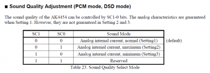
You now have access to the DAC settings and I wonder what the „sound quality“ tab and it‘s numbers 1 to 3 are there for...
Best regards,
Frederik
has anyone tried out the new version of the Hypex Filter Designer (4.8) and it‘s accompanying new firmware v1.3 for the Fusion Amps?
You now have access to the DAC settings and I wonder what the „sound quality“ tab and it‘s numbers 1 to 3 are there for...
Best regards,
Frederik
I note the comments but these are being done using ARTA ?
I will read up on the Arta notes to see if it helps me.
Im still trying to find out how to do alignment using the Hypex software
I have a copy the original DLCP user manual D1, Page 22 just below fig23
" A way of obtaining quasi anechoic low frequency measurements is making close up measurements. Working with such measurements requires a good deal of interpretation but it is doable".
requires a good deal of interpretation doesnt fill my level of competence with confidence, I still think my best option would be to do line up outside in Free Space and minimise any reflections ?
Im finding I can only get so far in trying the Hypex Filter Design software without a fusion amp connected to my PC - now in a catch 22 - do I buy and hope Ill get what I expect or wait till a full explanation and all the potential problems are out in the open, with solutions.
You now have access to the DAC settings and I wonder what the „sound quality“ tab and it‘s numbers 1 to 3 are there for...
Don't know what it does exactly, but the amp's noise floor increased significantly with settings other than 1.
I found this in the DAC chip's datasheet:
Attachments
Last edited:
Near field (up to 1cm) doesn't show baffle diffractions. 1 meter and gating 6ms is good for can above 1kHz. For W-M xo is more difficult, ground plane or outdoors 20ms gating. Room eq after that.
Timing adjustment is necessary for 2-way and M-T of a 3-way. 20 microseconds delay for tweeter is good starting point. Look at step response and SPL summation, also with inverted polarity.
Timing adjustment is necessary for 2-way and M-T of a 3-way. 20 microseconds delay for tweeter is good starting point. Look at step response and SPL summation, also with inverted polarity.
Step-by-step guide to setting up active speakers in-room
I tried different approaches to configuring active speakers and found the approach shown below to be the simplest yet giving very good results. I don't use FusionAmps. However, you should be able to adapt it to the Hypex software since all necessary parts are there.
I have no place where to make outside measurements. In-room measurements are enough.
I'm using REW.
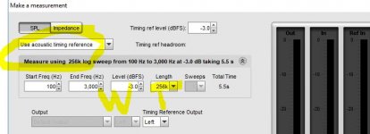
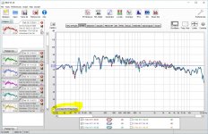
First, we need to find particular driver delays. I place a mic in my listening position and measure every driver with a tweeter as an acoustic timing reference:

This gives me how many milliseconds are woofers behind the tweeter or vice-versa. I setup delays for every driver.
During the measurement I also check that all drivers are connected in positive polarity. We can find this information in the Impulse tab. The impulse should point to the top of chart, not bottom.
I configure crossovers after that. Linkwitz Ryley 24- or 48 dB/octave give very good results. Choose a crossover point where both drivers are still linear so that you don't need corrections. By saying linear I mean that both drivers should show flat frequency and phase response at the crossover point.
When crossovers are ready, perform swipes acrosso the listening position. I adhere to structure recommended at avsforums for configuring Odyssey. First measurement is in the best position at ear level. You measured delays from that position. I measure both speakers from that position.
Then I move the mic about 10 cm closer to the speakers. Measure both. I lift the mic about 10 cm and measure again. Move the lifted mic back to the first position and measure from there. You will get 8 measurements in total.
Always measure left channel first, right second. Keeping this order you will be able to easily distingiush left and right measurements within these 8 measurements you will make. Left measurements will be odd, right measurements will be even.
Do not use gating when making measurements. Leave standard 500ms gate window. You're correcting for the in-room response, so you don't have to try to remove the room from the equation.
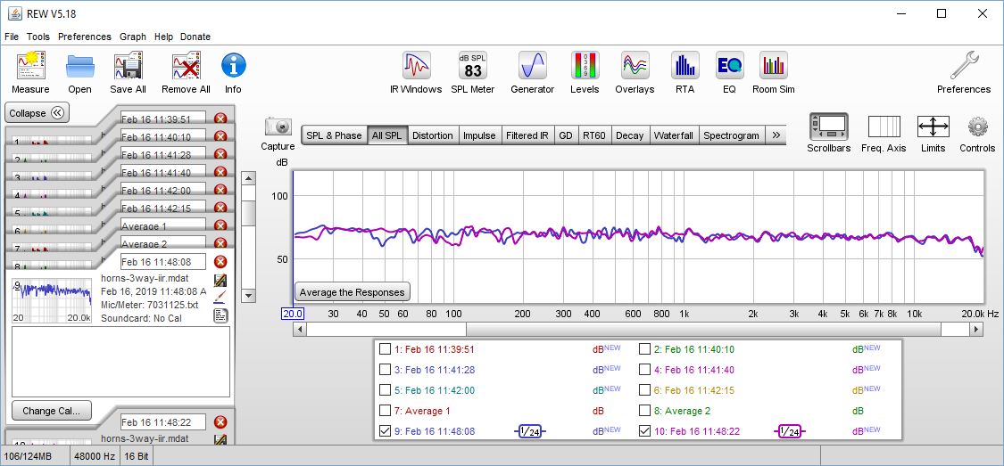
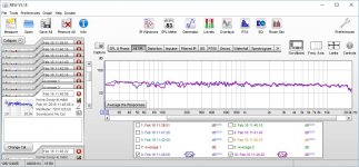
Select only left measurements and average them:
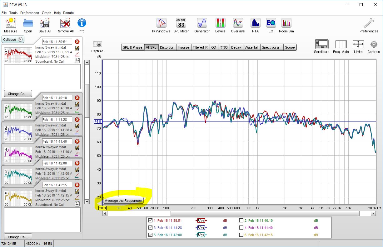
Do the same for the right measurements. You will get left and right measurements averaged by 4 positions.
* On the screenshot above I have enabled 1/24 smoothing. You may do as well. Please click Graph - Apply 1/24 smoothing.
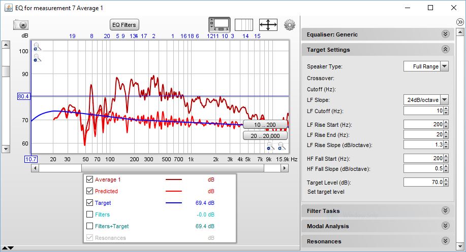
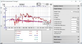
After I got two new frequency charts, I use the Eq feature to generate a set of filters for my equalizer. There you will need to set target level and how much high-frequencies will decrease.
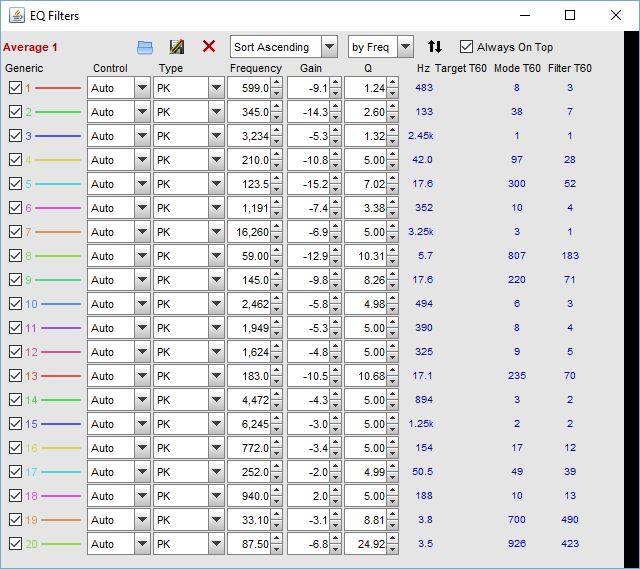
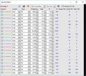
Then I export these filters into my equalizer. I'm using Equalizer APO and it accepts text files right from the REW. You may need to copy filters manually into the Hypex software. You can get a list of filters by clicking on "EQ Filters" button.
After uploading the EQ filters into the equalizer, I perform two control measurements. You should get a reasonably smooth response.
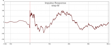
If you used linear-phase crossover, the step response should look like that:
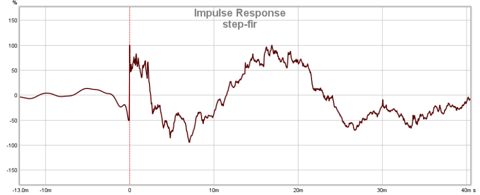
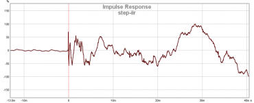
with minimum phase filters, it will look like that:
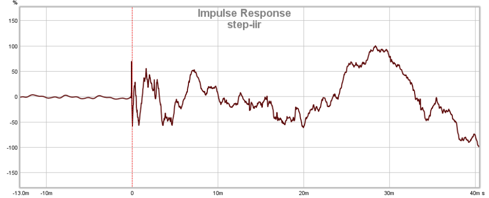
Since FusionAmps use BiQuads for correction, you're likely to get a chart similar to the second one.
This approach takes into account all baffle and room effects. To my ears it works well.
I tried different approaches to configuring active speakers and found the approach shown below to be the simplest yet giving very good results. I don't use FusionAmps. However, you should be able to adapt it to the Hypex software since all necessary parts are there.
I have no place where to make outside measurements. In-room measurements are enough.
I'm using REW.
First, we need to find particular driver delays. I place a mic in my listening position and measure every driver with a tweeter as an acoustic timing reference:
This gives me how many milliseconds are woofers behind the tweeter or vice-versa. I setup delays for every driver.
During the measurement I also check that all drivers are connected in positive polarity. We can find this information in the Impulse tab. The impulse should point to the top of chart, not bottom.
I configure crossovers after that. Linkwitz Ryley 24- or 48 dB/octave give very good results. Choose a crossover point where both drivers are still linear so that you don't need corrections. By saying linear I mean that both drivers should show flat frequency and phase response at the crossover point.
When crossovers are ready, perform swipes acrosso the listening position. I adhere to structure recommended at avsforums for configuring Odyssey. First measurement is in the best position at ear level. You measured delays from that position. I measure both speakers from that position.
Then I move the mic about 10 cm closer to the speakers. Measure both. I lift the mic about 10 cm and measure again. Move the lifted mic back to the first position and measure from there. You will get 8 measurements in total.
Always measure left channel first, right second. Keeping this order you will be able to easily distingiush left and right measurements within these 8 measurements you will make. Left measurements will be odd, right measurements will be even.
Do not use gating when making measurements. Leave standard 500ms gate window. You're correcting for the in-room response, so you don't have to try to remove the room from the equation.
Select only left measurements and average them:
Do the same for the right measurements. You will get left and right measurements averaged by 4 positions.
* On the screenshot above I have enabled 1/24 smoothing. You may do as well. Please click Graph - Apply 1/24 smoothing.
After I got two new frequency charts, I use the Eq feature to generate a set of filters for my equalizer. There you will need to set target level and how much high-frequencies will decrease.
Then I export these filters into my equalizer. I'm using Equalizer APO and it accepts text files right from the REW. You may need to copy filters manually into the Hypex software. You can get a list of filters by clicking on "EQ Filters" button.
After uploading the EQ filters into the equalizer, I perform two control measurements. You should get a reasonably smooth response.
If you used linear-phase crossover, the step response should look like that:
with minimum phase filters, it will look like that:
Since FusionAmps use BiQuads for correction, you're likely to get a chart similar to the second one.
This approach takes into account all baffle and room effects. To my ears it works well.
Attachments
Last edited:
I am not convinced if building crossover this way is a good idea.
Proper way is to use HFD for taking measurements and applying filters. This software does the same thing as REW - it outputs log sweep, captures result, truncates impulse response to semi-anechoic and allows to apply filters directly to DSP! Just use it with analog input of Hypex DSP module (can be Fusion or DLCP) and analog output from USB soundcard. This is recommended method.
If you have no Hypex gear in possession or you don't like HFD from some unknown reason, you can measure and tune your system using REW and UMIK-1 mic. Apropriate timings between drivers can be set after applying crossover correctly, by null depth chcecking after polarity inversion.
How to apply crossover correctly:
Voila, you now have properly set active crossover which tracks phase perfectly in broad range, offering you coherent sound. NOW, you can take measurements without gating, at your listening position. Measure L and R channel and equalize it independently. Do not try to correct nulls caused by floor or front wall cancellation it occurs frequently in 150-450Hz range. Rather cut peaks or apply narrow-band shelves. Do not mix loudspeaker equalizing filters set at the design stage, with filters applied after in-room response measurement, it will be convenient for you.
Proper way is to use HFD for taking measurements and applying filters. This software does the same thing as REW - it outputs log sweep, captures result, truncates impulse response to semi-anechoic and allows to apply filters directly to DSP! Just use it with analog input of Hypex DSP module (can be Fusion or DLCP) and analog output from USB soundcard. This is recommended method.
If you have no Hypex gear in possession or you don't like HFD from some unknown reason, you can measure and tune your system using REW and UMIK-1 mic. Apropriate timings between drivers can be set after applying crossover correctly, by null depth chcecking after polarity inversion.
How to apply crossover correctly:
- Switch off any EQ or crossovers and measure each driver's full-band raw response independently, using the same mic position. Use time-gated measurement with as long direct-to reflected sound arrival as it's practically possible.
- Equalize raw response of each driver to flat using set of IIR filters available in REW or HFD, (if you are thankfully using HFD). Equalize tweeter to minimum 3 octaves below and woofer 3 octaves above predicted 4-th order crossover point. If using 2-th order crossover, you should equalize it fullband which is tricky and already dangerous to fragile tweeters.
- Set levels of woofer and tweeter precisely at the same value. Frequancy response curves from both channels should overlap each other perfectly in as broad range around crossover, as possible.
- Apply Linkwitz-Riley 4-th order crossover on woofer and tweeter. In case of woofer/midrange it is sometimes good to use 2-nd order LR crossover network. If you believe in other crossovers schemes I'll leave you on your own, I'm sorry.
- Now, invert polarity of tweeter and measure summed response of both drivers. Set delay for tweeter using trial-and-error method and conduct measurement of summed response each time, until null is the deepest. Do not forget to back to normal polarity after this!
Voila, you now have properly set active crossover which tracks phase perfectly in broad range, offering you coherent sound. NOW, you can take measurements without gating, at your listening position. Measure L and R channel and equalize it independently. Do not try to correct nulls caused by floor or front wall cancellation it occurs frequently in 150-450Hz range. Rather cut peaks or apply narrow-band shelves. Do not mix loudspeaker equalizing filters set at the design stage, with filters applied after in-room response measurement, it will be convenient for you.
Last edited:
I noticed the target curve is set about -10dB below the actual measured response curve, is that to get the gain structure right? or?
Could you possibly post some pictures of the frequency response of the xover and EQ?
Target curve is about -10dB below measured to avoid a dip below 100Hz. It's a dipole speaker that loses sensitivity below 100Hz. I equalize all frequencies to sound as loud as 80Hz.
There is a screenshot of the final frequency response where I'm talking about checking the equalizer settings. There is also a set of my filters. However, don't copy them. Your speaker and took will require a different set.
I wish I could post more, but now I'm at the hospital.
Ouch! Hopefully nothing serious?
Thanks, Yes and no. My 3-year old son probably has pneumonia and I was told he will need to spend 10 days there..
Sorry to hear! Not fun

Equalize raw response of each driver to flat using set of IIR filters available in REW or HFD, (if you are thankfully using HFD). Equalize tweeter to minimum 3 octaves below and woofer 3 octaves above predicted 4-th order crossover point. If using 2-th order crossover, you should equalize it fullband which is tricky and already dangerous to fragile tweeters.
(...)
Apply Linkwitz-Riley 4-th order crossover on woofer and tweeter.
Hello Windforce85,
I have been using this method for years, but have moved on to something different now.
The positive point about this method is that you can apply any electrical filter and get the equivalent acoustical response, meaning you can try different crossover frequencies and slopes without changing EQ settings. This is more flexible than directly trying to match a given target for sure.
But this method also has drawbacks:
- You need many EQ points far in the stopband to get it flat (magnitude and phase) in and around the passband. This can be a problem when the number of biquads is limited (15 in the case of the fusion amp, including filters, not enough for a JBL M2 correction for example).
- You will need "aggressive" EQ (both in term of Q and gain) to get a somewhat flat phase in the passband, often leading to peaks in the stopband.
- These "aggressive" EQ points in LF will bring quantization errors, hence noise (not necessarily audible with a good biquad implementation, but still not satisfying).
In the end I found it easier to directly shoot for a given acoustical filter target, using things like shelving filters and an approach similar to a Linkwitz transform.
Hypex has an "asymmetrical shelving" LT implementation that is handy for this kind of things.
Shooting for a given target is not easy, so you can also use the rePhase software as a simulation tool: I have implemented a "compensate" filter mode that makes this kind of approach easier, working like a generalized two-step LT:
- After loading a measurement you set your intended HP/LP acoustical filters target in the "minimum-phase filters" tab, and turn them into "compensate" filters, meaning they will do the opposite of the real filters (ie they will go up in the stopband!).
- You then play with filters and a touch of EQ to get a flat magnitude and phase response as far as possible (up to the noise floor of the original measurement, which being originally flat will be rising because of the compensate filter).
- You then remove the compensate filters and you have got your EQ/filter settings to get the intended acoustical target. EQ and filter settings can be reported in your DSP.
You can also use these compensate filters to account for any HP filter you might have used during the measurement process to protect a fragile driver.
Poor kid, that is a long timeThanks, Yes and no. My 3-year old son probably has pneumonia and I was told he will need to spend 10 days there..
That said kids seem to adapt pretty well to this kind of situation.
I hope everything goes well!
Thanks pos! I'm certain everything will be OK he is little man, but strong one! I did play a bit with rePhase but I must admit not to that level, so in fact I have not familiar with this method. If I understand it correctly, it looks very similar in its principles becouse it leads to acoustical slopes which must closely resemble its mathematical equivalents - this is basically all what is needed in end result.
I tend not to agree about excessive amount of filters usage. Importatnt thing is to learn using them efficiently. In 90% cases I operate on shelves / assymetrical shelves only. It is very effective way of targetting SPL nonlinearities. I've made W22EX001 ruler-flat till 10 kHz using just 6 filters. I managed break-up peak and its surrounding completely just using one HP and one LP shelf. If I remember correctly, I used only 4 filters for equalizing DXT tweeter from 250 Hz right to the top.
I also moved away from 'one proper' method a bit. Rather than stick to on-axis response only, I gather +/-60 degree horizontal measurements bundle and operate on simulated power-response inside of VituixCAD. Its directivity plots are a real weapon. I can precisely target directivity and diffraction issues and judge what to correct and to what extent. I use minimum amount of filters possible and aim for overall balance rather than going to the war with all those wrinkles. Simulations are very accourate becose corrected loudspeaker behaves nearly idetically in reality. Sonically, these filters are superior to on-axis measurement methodology from simple reasons.
I managed to find DXT tweeter data, actually it was 5 filters and it was uncertain below 1kHz becouse I was testing various things...
In attachment:
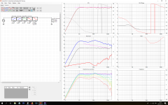
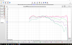
Simulation based on raw response measurements and... the measurements (watch 2dB grid):
I tend not to agree about excessive amount of filters usage. Importatnt thing is to learn using them efficiently. In 90% cases I operate on shelves / assymetrical shelves only. It is very effective way of targetting SPL nonlinearities. I've made W22EX001 ruler-flat till 10 kHz using just 6 filters. I managed break-up peak and its surrounding completely just using one HP and one LP shelf. If I remember correctly, I used only 4 filters for equalizing DXT tweeter from 250 Hz right to the top.
I also moved away from 'one proper' method a bit.
Rather than stick to on-axis response only, I gather +/-60 degree horizontal measurements bundle and operate on simulated power-response inside of VituixCAD. Its directivity plots are a real weapon. I can precisely target directivity and diffraction issues and judge what to correct and to what extent. I use minimum amount of filters possible and aim for overall balance rather than going to the war with all those wrinkles. Simulations are very accourate becose corrected loudspeaker behaves nearly idetically in reality. Sonically, these filters are superior to on-axis measurement methodology from simple reasons.I managed to find DXT tweeter data, actually it was 5 filters and it was uncertain below 1kHz becouse I was testing various things...
In attachment:
Simulation based on raw response measurements and... the measurements (watch 2dB grid):
Attachments
Last edited:
- Home
- Amplifiers
- Class D
- The New Hypex Fusion Plate amps