What do you feel about Sure versus 3e-audio TPA3255 board
3e-Audio has proven very good audio quality and is well made.
This topic is for TPA3116D2.
TPA3255 topics are:
TPA3255 - all about DIY, Discussion, Design etc.
What is wrong with TPA3255?
TI TPA3255EVM
TPA3255 topics are:
TPA3255 - all about DIY, Discussion, Design etc.
What is wrong with TPA3255?
TI TPA3255EVM
Last edited:
i was kinda worried that it wont operate optimally in higher voltage than recommended. thanks!!
It should do fine. 19-20V/6A will also do fine.
i was kinda worried that it wont operate optimally in higher voltage than recommended. thanks!!
A TPA3116 chip can operate with an absolute maximum voltage of 26V. In practice, the supply voltage should not exceed 24V. Apart from the voltage rating of the TPA3116 chip, the voltage rating of the capacitors is important. Most boards use 35V rated capacitors but some only 25V rated capacitors. For boards with 25V rated capacitors, 25V is too close to a 24V supply and I suggest 19-20V supply.
You should NEVER use a higher supply voltage than recommended without first investigating why this value is stated as the recommended maximum voltage.
Have you seen this new 2.1 TPA3116D2 boards TPA3116D2 2x 80W +100W 2.1 channel digital subwoofer power amplifier board WMNE | eBay
they look like some older ones []Fasdga Amplifier Board TPA3116D2 50Wx2+100W 2.1 Channel Digital Subwoofer P L9V9 192090219544 | eBay witch i heard have some problems.
Have anyone tried one of those new black ones?
they look like some older ones []Fasdga Amplifier Board TPA3116D2 50Wx2+100W 2.1 Channel Digital Subwoofer P L9V9 192090219544 | eBay witch i heard have some problems.
Have anyone tried one of those new black ones?
Have you seen this new 2.1 TPA3116D2 boards TPA3116D2 2x 80W +100W 2.1 channel digital subwoofer power amplifier board WMNE | eBay
they look like some older ones []Fasdga Amplifier Board TPA3116D2 50Wx2+100W 2.1 Channel Digital Subwoofer P L9V9 192090219544 | eBay witch i heard have some problems.
Have anyone tried one of those new black ones?
I have the same but with red PCB. Same chokes, same OPA. It works. I think its not one of the best but not the worst. I don't know inductance of output choke.
For me it's: Sub channel HKTS200 (4R) subwoofer and satellite Cabasse (8R) speaker.
I have the same but with red PCB. Same chokes, same OPA. It works. I think its not one of the best but not the worst. I don't know inductance of output choke.
For me it's: Sub channel HKTS200 (4R) subwoofer and satellite Cabasse (8R) speaker.
This ones do not have a high pass, right? But hey do have a low pass for the sub?
3e-Audio has proven very good audio quality and is well made.
I recently received my 3e TPA3255 modules and indeed they are very well made. Super quality of construction. The only nit is use of no name “ChongX” caps for the main rails. An amp of this quality should use some reputable name brand cap like Nichicon, Panasonic, etc.
It would be nice to make an open-source DIYA variant which allows us to use caps of our own choosing and I would use Molex positive lock connectors with 16ga wires for power and speakers. I don’t like green plastic screw terminals for power in and speaker out for lack of reliability.
This ones do not have a high pass, right? But hey do have a low pass for the sub?
Exactly: only low pass.
i doubt if this makes a difference but it sure looks better(to me)
An externally hosted image should be here but it was not working when we last tested it.
Have a TPA3116 blue/black module I just received and there's solder flowing across several of the pins but it all seems to work fine. All the other modules I've had have been very neat with spaces between each pin.
Amazingly there doesn't seem to be any shorts.
Amazingly there doesn't seem to be any shorts.
Attachments
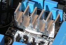
Have a TPA3116 blue/black module I just received and there's solder flowing across several of the pins but it all seems to work fine. All the other modules I've had have been very neat with spaces between each pin.
Amazingly there doesn't seem to be any shorts.
Check the pinning in the data sheet - and you will find that solder flow does not do any harm.
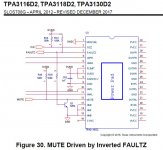
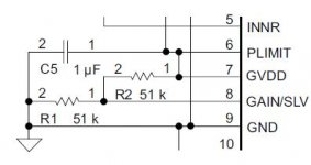
I have a question on the gain/impedance settings for the 3116/3118 chips. From the datasheet I infer that GVDD is a voltage source for the R2/R1 voltage dividing network. The GAIN/SLV pin senses the voltage at the R2/R1 junction and sets the gain and input impedance according to one of 8 voltages ranges that are determined by the different resistor combinations.
My question concerns the 20 dB MASTER gain setting. The data sheet specifies an open for R2 and 5.6K for R1. Since R2 is open the GAIN/SLV pin should sense 0 volts so how important is the R1 value? I'm considering modifying an amp that is set to MASTER mode with 32 dB gain (R1 = 39K, R2=100K) by just removing R2 and leaving R1 as is. Problems?
My question concerns the 20 dB MASTER gain setting. The data sheet specifies an open for R2 and 5.6K for R1. Since R2 is open the GAIN/SLV pin should sense 0 volts so how important is the R1 value? I'm considering modifying an amp that is set to MASTER mode with 32 dB gain (R1 = 39K, R2=100K) by just removing R2 and leaving R1 as is. Problems?
Attachments
bluetooth amp board
I just received this little integrated 2 channel bluetooth/3116 board and I can say I am very impressed. It is abolutely quiet, phone connects quickly and it doesn't run too hot on a 19v laptop power supply. I paid 6 GBP for this board.
TPA3116 50W+50W Bluetooth Digital Amplifier Board Module Amplifier Board | eBay
I have a question on the gain/impedance settings for the 3116/3118 chips. From the datasheet I infer that GVDD is a voltage source for the R2/R1 voltage dividing network. The GAIN/SLV pin senses the voltage at the R2/R1 junction and sets the gain and input impedance according to one of 8 voltages ranges that are determined by the different resistor combinations.
My question concerns the 20 dB MASTER gain setting. The data sheet specifies an open for R2 and 5.6K for R1. Since R2 is open the GAIN/SLV pin should sense 0 volts so how important is the R1 value? I'm considering modifying an amp that is set to MASTER mode with 32 dB gain (R1 = 39K, R2=100K) by just removing R2 and leaving R1 as is. Problems?
No problems with that.
- Home
- Amplifiers
- Class D
- TPA3116D2 Amp