Yes. Your board looks like it has the "original" (always questionable with Chinese boards and T.I. doesn't help at all if you ask them about the chips in the photo). What driver is your full-range ? By the way, it is not a fair comparison (class-D to class-A). If you want better sound you have to get your hands dirty (a little) and get your soldering iron. First of all you have to replace that 8 awful ceramic capacitors. There is another thread with modifications for the TPA3116D2 boards
Last edited:
They are standart Aiyama 4 inch china full ranges. ( Afaik they are clone of Diatone full ranges) They sound good in 5 liters sealed birch plywood boxes.
System sounds good when listening but when switched to a class A amp like Jlh there is warmer sound and more air.And hear more instruments ,I heard piano sound which I was not aware when listening class d when I switched to class A
System sounds good when listening but when switched to a class A amp like Jlh there is warmer sound and more air.And hear more instruments ,I heard piano sound which I was not aware when listening class d when I switched to class A
I left my TPA3116D2 board aside and I use a slightly modified TDA7379 + NE5532 linear (BTL) amplifier board (Chinese also) as my everyday mule. For peace of my ears and mind.Well as I wrote before, for better sound https://www.diyaudio.com/community/threads/tpa3116d2-boards.252663/System sounds good when listening but when switched to a class A amp like Jlh there is warmer sound and more air.And hear more instruments........
Elias

The board will not sound like an original TPA3116 as long as you do not replace the fake NE5532 opamps.
They spoil the sound of many of these basically quite good builds. Can be quite surprising, if you install a real NE5532, as these fakes are just ridiculous ugly sounding. Do not put in any "better" opamp, a real NE is excellent in this buffer position.
They spoil the sound of many of these basically quite good builds. Can be quite surprising, if you install a real NE5532, as these fakes are just ridiculous ugly sounding. Do not put in any "better" opamp, a real NE is excellent in this buffer position.
I have original ne5532s in my storehouse. Will change them tomorrow and check. It is good that the board has sockets
If I remember correctly, this is one of the not-so-great TPA3116 examples.Yes. Your board looks like it has the "original" (always questionable with Chinese boards and T.I. doesn't help at all if you ask them about the chips in the photo). What driver is your full-range ? By the way, it is not a fair comparison (class-D to class-A). If you want better sound you have to get your hands dirty (a little) and get your soldering iron. First of all you have to replace that 8 awful ceramic capacitors. There is another thread with modifications for the TPA3116D2 boards
In general, Chinese TPA3116 boards should have their gains lowered to keep the noise floor under control (which may explain the "class-D to class-A difference").
The gain is more than enough. I already can not give more than quarter of total volume.Sb acoustics Woofer have 93db sensitivity.
Yes, the high gain is a problem. Chinese "developer" think that an amp seems more powerfull, if even a very small input makes it blast at full throttle.
They know nothing about and don't care for noise and reasonable line levels. You can not compare a Chinese design decission with what you learn in a Western technical school or university. In China is all about ignoring rules to get an advantage over others that offer products based on the same chip.
If you have a large, uneducated customer base, this may even pay of. If we decide to buy their stuff, we got to put it right or live with it. Some more expensive or better designed modules have jumpers to adjust gain to useable levels.
With your board, you have to change a two resistor combination to get a lower gain and a better SNR. Read the TPA3116 data sheet and identify them on your board. Usually they are close to the chip, maybe under the heat sink. Not hard to do.
These boards also have turn on pop which i did not like.They also could make a little circuit to eliminate this problem.But yes Chinese "developer" philosophy. Cheaper sells more. They could make better designs and we can pay for it some more bucks.
Good afternoon everyone.
Recently I received such a 2.1 amplifier based on two tpa3116d2, one microcircuit in the bridge for the subwoofer channel, the second for the left and right channels.
The question is the following: at about 30-35% of the volume level, the subwoofer channel begins to clip (I connected an oscilloscope - the sine wave is distorted) and, accordingly, the subwoofer begins to produce incorrect sounds, while the left and right channels operate without distortion at almost maximum volume.
For power supply I use a 24v 10a pulsed unit, there is no voltage drop when adding power.
What could be the problem?
Thanks in advance everyone
Attachments
There are many things to check. Is the sub 3116 chip actually configured for mono, compare to the TI data sheet?
With your scope measure the output voltage when clipping, with a 24 volt supply it should be around 24 volt peak to peak if you use one probe and about 48 volt peak to peak with using 2 scope probes measuring differentially.
The sub may be less efficient than your stereo speakers and you may be using more gain on the sub channel vs the stereo chip.
The output inductors on the sub channel may be saturating and not be able to handle 6 amps peak current.
The opamps that control the frequency response of the sub could not be biased correctly and not operating at the halfway point of the power supply. Check the DC voltage at the output of the opamps it should be 1/2 the supply voltage.
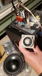
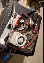
Here is what I did to eliminate the power-on "pop" transient that afflicts these cheap 2.1 boards. The pop transients literally destroyed the small subwoofer driver it was connected to within a month of using it. After replacing the sub driver, I decided to protect it using a time delay relay. These photos show the Omron H3CR programmable delay timer that I installed and configured such that its relay contacts remain open for about 5 seconds upon power-up then they close. I connected the subwoofer wiring in series with the relay contacts. It works perfectly. The H3CR timer is commonly found on ebay used or as surplus NOS. There are less expensive and smaller alternatives but I already had some of these timers sitting around in my parts inventory. You may also need an octal socket to plug the relay into if you use the H3CR.
Attachments
Beautiful, I would like to replicate it. Would it be convenient to provide a schematic or some detailed production instructions?My first TPA3116 design started in 2014. Since then I enjoy these driving small guitar amps with 6 inch drivers. This is my actual pcb, providing some features useful for battery operation such as under-voltage lockout and an automagic watchdog shutdown.
Would it be possible to use the TPA3116 in "inverting summing" mode by swapping RINP and RINN and obtain a similar circuit as shown in this diagram?

I ask this because when I disconnect one of the two input signals to RINP, the other changes volume and it is very unpleasant. Is this a normal behavior or is it an error in my configuration?
I ask this because when I disconnect one of the two input signals to RINP, the other changes volume and it is very unpleasant. Is this a normal behavior or is it an error in my configuration?
The functional block diagram (datasheet 7.2) gives the answer.
Each amp is driven by a differential inv amp.
The inputs are connected to the pins via series resistors to program overall voltage gain.
Thus there is no direct access to internal summing nodes.
So the answer must be no.
Each amp is driven by a differential inv amp.
The inputs are connected to the pins via series resistors to program overall voltage gain.
Thus there is no direct access to internal summing nodes.
So the answer must be no.
- Home
- Amplifiers
- Class D
- TPA3116D2 Amp