Hello! I recently bought a classic 2.1 TPA3116 bluetooth board, this one (in black colour). It looks identical to the Aiyima boards except for the different colour. The chip should be original seeing the solder pads on the other side of the board (definitely not one of the "domestic chips").
However i found out the high pass filter (selectable through the tiny switch) works differently in the two stereo channels: the right channel has a much higher frequency cutoff compared to the left channel; it seems to work on both as there's a reduction in excursion on both channels, but the left one moves way more than the right one with the filter on.
Does anyone know how the high pass filter is configured on the board and maybe which components to look at (before i reverse engineer it)? I personally suspect it's a simple 6dB high pass filter inserted at the input of the opamp that controls the satellite volume, but i might be wrong.
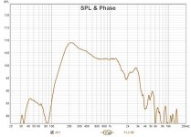
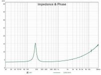
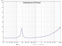
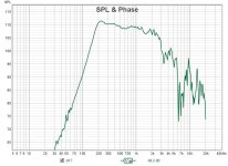
Adding details: the satellite enclosures are 0.35L with one SB Acoustics SB10PGC21-4 each; i verified the enclosure is properly sealed through an impedance measurement, both produce a clean curve with a peak at 200Hz. A nearfield response measurement reveals the issue with the filter (do note the low frequency response below resonance probably comes from the two "subwoofers" which were connected during the measurement, and are placed very close to the midranges).
The two drivers haven't been broken in yet which should explain the slight impedance difference, or maybe the damping material is inconsistent between the two enclosures (i didn't weight it).
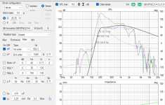
From a Vituixcad simulation (ignore the voltage level) it looks like the left channel might barely have a 80hz high pass while the right channel corresponds to something like 500Hz (both first order).
However i found out the high pass filter (selectable through the tiny switch) works differently in the two stereo channels: the right channel has a much higher frequency cutoff compared to the left channel; it seems to work on both as there's a reduction in excursion on both channels, but the left one moves way more than the right one with the filter on.
Does anyone know how the high pass filter is configured on the board and maybe which components to look at (before i reverse engineer it)? I personally suspect it's a simple 6dB high pass filter inserted at the input of the opamp that controls the satellite volume, but i might be wrong.
Adding details: the satellite enclosures are 0.35L with one SB Acoustics SB10PGC21-4 each; i verified the enclosure is properly sealed through an impedance measurement, both produce a clean curve with a peak at 200Hz. A nearfield response measurement reveals the issue with the filter (do note the low frequency response below resonance probably comes from the two "subwoofers" which were connected during the measurement, and are placed very close to the midranges).
The two drivers haven't been broken in yet which should explain the slight impedance difference, or maybe the damping material is inconsistent between the two enclosures (i didn't weight it).
From a Vituixcad simulation (ignore the voltage level) it looks like the left channel might barely have a 80hz high pass while the right channel corresponds to something like 500Hz (both first order).
Attachments

Last edited:
Here's a follow-up and solution to the previous issue.
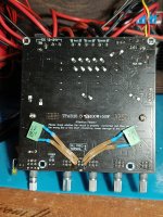
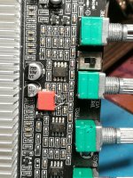
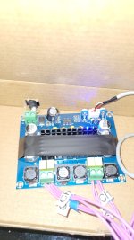
As i suspected the high pass filter is a simple 6dB filter made with a capacitor in series to the rest of the circuit, which i guess is responsible for the treble EQ and satellite channels volume. You can see them in the first picture, i painted them pink to make them visible. The switch on the board simply shorts them so there's no high pass filter.
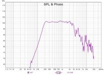
In my case the one on the top (for the right channel) had a value of 4.7nF, which filters at around 500Hz; the one on the bottom was around 40nF, so it filtered at something like 80Hz, which in my case was too little filtering.
I then replaced the bottom capacitor with a 4.7nF one i had, then added to both channels 2.2nF capacitors in parallel to the others and glued those to the back; this way i have 6.9nF of capacitance and a high pass around 300-350hz, which is ideal in my project. Adding capacitors is easy as they can be soldered directly to the switch leads on the bottom of the board; changing them on the top side is a bit more difficult (hence why i changed only one; i also didn't have two 6.8nF capacitors on hand).
I attached also the nearfield frequency response of the satellite with the 40nF capacitor, the satellite with the 4.7nF capacitor and the final response (equal on both) with 6.9nF; ignore the SPL average as it's wrong.
As i suspected the high pass filter is a simple 6dB filter made with a capacitor in series to the rest of the circuit, which i guess is responsible for the treble EQ and satellite channels volume. You can see them in the first picture, i painted them pink to make them visible. The switch on the board simply shorts them so there's no high pass filter.
In my case the one on the top (for the right channel) had a value of 4.7nF, which filters at around 500Hz; the one on the bottom was around 40nF, so it filtered at something like 80Hz, which in my case was too little filtering.
I then replaced the bottom capacitor with a 4.7nF one i had, then added to both channels 2.2nF capacitors in parallel to the others and glued those to the back; this way i have 6.9nF of capacitance and a high pass around 300-350hz, which is ideal in my project. Adding capacitors is easy as they can be soldered directly to the switch leads on the bottom of the board; changing them on the top side is a bit more difficult (hence why i changed only one; i also didn't have two 6.8nF capacitors on hand).
I attached also the nearfield frequency response of the satellite with the 40nF capacitor, the satellite with the 4.7nF capacitor and the final response (equal on both) with 6.9nF; ignore the SPL average as it's wrong.
Attachments


This is my XH-M543....
I've been using it every day since I got it exactly 2 weeks ago.
Already the input gain potentiometers went bad - had to adjust them almost daily. Today one of the channels was very grainy sounding, and the volume had dropped a lot since earlier in the day, so I finally swapped them and the amp is sounding great again.
I found some replacements I had bought a while back. They seem to be a bit better quality, hopefully they hold up. I couldn't find my nicer quality 10k pots.
I also replaced that 22uf capacitor near the power input, not for any particular reason, just to note it's not original.
Btw, I bought my board from Amazon, despite what the pictures of the listing show, the board I received has inductors marked 100 and output film capacitors marked 105J63
I have the board powered by an old Gateway 19V 7A laptop power supply.
Sounds good.
Today I also found a bag of 330uF 63V Panasonic capacitors I never used. I considered replacing those surface mount 330uf with them, but the Panasonic capacitors were thru-hole, so it would be annoying to install them.
Attachments
Last edited:
You guys seem more knowledgeable about the aliexpress boards, I want to power two speakers with the following specifications and I'm not sure which one to go for
Just need something around like $10 just to power them for now, I intend to buy a proper one in the future with other speakers.
Not sure how much power I will actually need for them or what boards to go for, that's the main issue, seems like the power supply matters a lot for some chips as well and I feel kinda overwhelmed, Only thing is I need some sort of case around it and having bass/treble adjustment knobs along with the volume one would be great. As far as bluetooth or other fancy stuff I don't really care. Thanks in advance.
Bass reflex bookshelf type, 15cm 3-way system
Nominal impedance: 8Ω
Maximum power: 100 W
Woofer: 15cm cone type
Mid-range: 5.2cm cone type
Tweeter: 2cm dome type
Dimensions: 200 (W} x 310 (H) x 292 (D} mm
Weight: 4.2 kg
Sensitivity/dB: Not sure (maybe 96db)
Frequency response: Not sure (maybe 30Hz to 27000Hz)
Just need something around like $10 just to power them for now, I intend to buy a proper one in the future with other speakers.
Not sure how much power I will actually need for them or what boards to go for, that's the main issue, seems like the power supply matters a lot for some chips as well and I feel kinda overwhelmed, Only thing is I need some sort of case around it and having bass/treble adjustment knobs along with the volume one would be great. As far as bluetooth or other fancy stuff I don't really care. Thanks in advance.
https://www.aliexpress.us/item/3256802976839207.html?
@nicto, you can find variations of these black-case amps under $10. Fair warning: Many sellers sell two variants of the same amp with either real 3116 chip or a Chinese-made CS8673. Read buyers' reviews, carefully check your buying options, and read the product description (TPA3116 is typically displayed as "imported chip").
@nicto, you can find variations of these black-case amps under $10. Fair warning: Many sellers sell two variants of the same amp with either real 3116 chip or a Chinese-made CS8673. Read buyers' reviews, carefully check your buying options, and read the product description (TPA3116 is typically displayed as "imported chip").
Last edited:
@Karlsonate I'll look into these T100H's with the TPA chip. I also saw the YS-XPSM with TDA7498E and the ZK-1002T with TPA3116D2. Do you think any of those would be better if at the same price or better to stick with the T100H? Thank you.
@nicto go with the 1002T, people have shared their experiences using it here: https://www.audiosciencereview.com/.../review-wuzhi-zk-1002-mostly-subjektiv.15043/
I can't comment on the TDA7498E-based amps because I have much less experience with them, but many budget implementations are flawed:
I can't comment on the TDA7498E-based amps because I have much less experience with them, but many budget implementations are flawed:
@Karlsonate Yeah I will. Was only considering stronger ones because according to the specs the 1002T on a lot of these listings says 50w at 8ohms instead of 100.
20W x @12V, 8Ω 35W x 2@12V,4Ω
35W x 2@19V,8Ω 60W x 2@19V,4Ω
50W x 2@24V,8Ω 100W x 2@24V,4Ω
Why my Fosi Audio V1.0B with a mean well 24V power supply sounds better than the Aiyima A07 that everyone raves about?
Perhaps you wanted it to?
Or (choose from the following, not an exhaustive list, more than one may apply):
1. Your Fosi amp is a better match for your speakers
2. Your source is a better match to your Fosi
3. Your Meanwell PSU is a better match to your Fosi than the Aiyima PSU
4. You may have a duff Aiyima
5. Your Fosi amp setup (PSU, source & speakers) is a better match for your listening environment.
6. Your interconnects, power and speaker cables may be playing a part.
Whatever, enjoy it. And sell your Aiyima!
Same setup with both amps except the power supply (Aiyima with the stock 36V one).
The 3116D2 has dynamics, the Aiyima is just loud.Anyway, my 2p
The 3116D2 has dynamics, the Aiyima is just loud.Anyway, my 2p
If you want to improve on your Aiyima and not only bash the brand, consider replacing the NE5532 you will find inside with some NE5532 that you buy from a qualified seller like Mouser. I don't advise to spend money on any expensive Op-amp. The NE5532 is one of the best you can get, even ignoring it's low price.
I can not find the pictures of real/ fake I made, but you will see the difference.
I found fake NE5532 in my A07 and with the real one it sounds simply transparent now. The fake made it sound somewhat muddy, all instruments mashed up.
I can not find the pictures of real/ fake I made, but you will see the difference.
I found fake NE5532 in my A07 and with the real one it sounds simply transparent now. The fake made it sound somewhat muddy, all instruments mashed up.
I'm not in to bash the Aiyima.I tested the opamp and it measured fine in diode, unless this is not enough to proof that it's genuine.
How did you spot the fakes in yours?
How did you spot the fakes in yours?
If you are going to swap opamps, might as well get an OPA1642. I use and like 5532 bit for my best amps, I use 1642 or 1656. There is a more natural sound IMO.
I have the topping pa5 II and it keeps up with my quad 909 without a problem, and at less than half the price. No need for opamp changes, good quality components already installed.
But it gets to a point where the performance is so good you fall into the territory of diminishing returns
But it gets to a point where the performance is so good you fall into the territory of diminishing returns
Hello everyone,
Just an amateur hobbyist here.. Thanks for this amazing thread! I've been following this thread for quite some times, and manage to gather lots of useful information and now I'm about to start my own TPA3116 project. I have question on PBTL mode, especially on how to implement the bootstrap snubber. Since the output P & N are tied together, can I use just 1 snubber on each channel (one for OUT+ and one for OUT-).
I'm not really sure about this because the evaluation board is using 4 snubbers total for each bootstrap pins, and retain it even in the PBTL mode..
Or does bootstrap snubber even necessary in PBTL mode?
Attachments
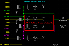
Since the bootstrap snubber mod was a diy add on to improve sound quality you can experiment with it in or off and use an Oscope to check for reduced overshoot or ringing. Technically, you could replace one cap with 66pF and change the resistor to 5ohms if you want to parallel and combine the two snubbers into one to save on parts placement.
Thanks @xrk971
I never saw any reports about these snubbers causing any problem so I will keep a pair of it on the layout. It just a matter of few passive components anyway.
My goal right now is to reduce components so I can have compact layouts because i'm going to use thru hole components. I have no special reason for going with thru hole parts, it just that I have few leftover of miniature size capacitors & resistor that I think will be perfect for this project. I will use spacers / shim on the top of the heatsink so I can put decoupling & bootstrap capacitors close to the chip..
I will use 68pF & 5.1R as per your advice as a backup plan..
A few years ago I built a 2.1 ch mini amplifier composed of a NE5532 preamplifier with tone controls and a board with TPA3116D2 all purchased on Amazon. I had inserted the two boards in two separate cheap aluminum containers and powered everything with an external HP power supply for notebooks 19V 4.7A and everything works fine.
In recent days I decided to change the container with a nicer one that I bought on eBay from Douk Audio.

Before proceeding I would like to address the problem of the six toroidal inductors that heat up tremendously. After a few minutes from switching on, even at idle, they reach 55 ° C to reach 70 at medium volume. Searching on the Web I found a thread on the Texas Instruments forum in which they suggest replacing the inductors with others of better quality because it seems that the heating is due to exaggerated losses in the toroidal cores. So I bought some Bourns 2000-100-V-RC 10µH 6.6A toroids on Mouser (542-2000-100-V-RC) they should arrive soon.
Has anyone already noticed this overheating of the inductors? If so, how did you solve it?

I also have another amplifier with TPA3116D2 with a different board layout, on this one (blue board) the inductors do not heat up at all, the toroids are black instead of yellow like on the other board, I removed one and measured it with the multimeter, it has an impedance of 17µH, however, yellow or black, both seem to me to have the winding with a wire of a section too small to be 6A, also the capacitors are 680nF on the blue board while on the red board they are 1µF. This blue board has the NE5532 SMD soldered so it is difficult to replace with the original ones which I did on the other board, but I must admit that it sounded good even with the ones already present. Before drilling the holes on the new cabinet panel I have to decide which of the two boards to use because the distance between the potentiometers is different: 22mm for the red one and 24mm for the blue one.
As you can see from the first photo, in my 2020 creation, I had added an anti-pop circuit, because the red board almost destroys the speakers when turned on and off, this does not happen on the blue board. Now I discovered that it is enough to add a resistor, a capacitor and a Schottky diode between the SDZ and Muting pins to solve the problem. Has anyone had the same problem? How did you solve it?
From measurements made, the amplifier at about 70% of the maximum power (with 2 Tannoy mercury mR cherry speakers and an 8 ohm subwoofer) does not absorb even at 1A. Without antipop, there is a peak absorption of about 2.5A at power on!
We all know that a linear power supply in the audio field is always better than a switching one and I thought of powering everything with an unused 18V, 60VA (so 3.3A) toroidal transformer that I have in a drawer together with a 6A diode bridge and 2x 4700 µF Nichicon electrolytics.
Or I can use a made in China 24V 6A switching power supply that I already have, this would significantly reduce the space occupied inside the case and improve the wiring.
Thanks for the suggestions.
In recent days I decided to change the container with a nicer one that I bought on eBay from Douk Audio.
Before proceeding I would like to address the problem of the six toroidal inductors that heat up tremendously. After a few minutes from switching on, even at idle, they reach 55 ° C to reach 70 at medium volume. Searching on the Web I found a thread on the Texas Instruments forum in which they suggest replacing the inductors with others of better quality because it seems that the heating is due to exaggerated losses in the toroidal cores. So I bought some Bourns 2000-100-V-RC 10µH 6.6A toroids on Mouser (542-2000-100-V-RC) they should arrive soon.
Has anyone already noticed this overheating of the inductors? If so, how did you solve it?
I also have another amplifier with TPA3116D2 with a different board layout, on this one (blue board) the inductors do not heat up at all, the toroids are black instead of yellow like on the other board, I removed one and measured it with the multimeter, it has an impedance of 17µH, however, yellow or black, both seem to me to have the winding with a wire of a section too small to be 6A, also the capacitors are 680nF on the blue board while on the red board they are 1µF. This blue board has the NE5532 SMD soldered so it is difficult to replace with the original ones which I did on the other board, but I must admit that it sounded good even with the ones already present. Before drilling the holes on the new cabinet panel I have to decide which of the two boards to use because the distance between the potentiometers is different: 22mm for the red one and 24mm for the blue one.
As you can see from the first photo, in my 2020 creation, I had added an anti-pop circuit, because the red board almost destroys the speakers when turned on and off, this does not happen on the blue board. Now I discovered that it is enough to add a resistor, a capacitor and a Schottky diode between the SDZ and Muting pins to solve the problem. Has anyone had the same problem? How did you solve it?
From measurements made, the amplifier at about 70% of the maximum power (with 2 Tannoy mercury mR cherry speakers and an 8 ohm subwoofer) does not absorb even at 1A. Without antipop, there is a peak absorption of about 2.5A at power on!
We all know that a linear power supply in the audio field is always better than a switching one and I thought of powering everything with an unused 18V, 60VA (so 3.3A) toroidal transformer that I have in a drawer together with a 6A diode bridge and 2x 4700 µF Nichicon electrolytics.
Or I can use a made in China 24V 6A switching power supply that I already have, this would significantly reduce the space occupied inside the case and improve the wiring.
Thanks for the suggestions.
Last edited:
Hi @Janux
That red TPA3116 kit looks familiar, similar like XH-M139..
I think couple years ago Mr. @CyberPit shared his detailed experience on that kit.
Please find his post below, there's link to his article :
Hope it helps,
Salwa
That red TPA3116 kit looks familiar, similar like XH-M139..
I think couple years ago Mr. @CyberPit shared his detailed experience on that kit.
Please find his post below, there's link to his article :
XH-M139 Issue
This 2.1 amp has (3) flaws:
1 - The leftmost knob is the full range left and right gain. In the middle of the range it has a hiss, but not at the lower or higher end of the range. I keep it pretty high and adjust volume via the laptop and the main volume knob on the right as an acceptable workaround.
2 - When I connect it to power, 90% of the time, the turn on thump is so loud that it goes into protect and does not work. If I disconnect the sub channel, apply power, and then reconnect the sub channel it functions, but I understand there is a mute pin on the...
Hope it helps,
Salwa
- Home
- Amplifiers
- Class D
- TPA3116D2 Amp