If Tom continues his current career trajectory he may have patients who severely try his patience. One of my favorite movies, "What About Bob", comes to mind.
Actually psychologists see clients. Psychiatrists see patients. "What About Bob". Great flick. "The Prince of Tides" springs to mind as well. If you need a good read for the summer, check out Irvin Yalom, "Lying on the Couch". Good story. Well written. Based on a true story, I believe.
I do enjoy helping people. It is always more fun to help someone who wants to help themselves, though. I'll have to get better at working with the clients who are stuck and aren't getting unstuck all that easily.
Tom
Last edited:
wiring is done but I have questions
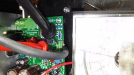
Tom, I set my meter to test continuity of connections in my, finally completed, Mod86 stereo amp. As I’ve mentioned, in my previous posts, I’m still wet behind the ears when it comes to electronics.
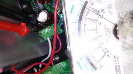
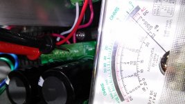
I didn’t expect to find continuity between the all component connection screws. The pics show the typical results with probes in contact with the screws and meter readings. You can see that the readings varied at different connections. Are these correct? I don't want to plug it in until it's right.
I also have about 5 more pics with the probes at different connections showing slightly different readings. I can post those if you like.
Thanks,
henry
Tom, I set my meter to test continuity of connections in my, finally completed, Mod86 stereo amp. As I’ve mentioned, in my previous posts, I’m still wet behind the ears when it comes to electronics.
I didn’t expect to find continuity between the all component connection screws. The pics show the typical results with probes in contact with the screws and meter readings. You can see that the readings varied at different connections. Are these correct? I don't want to plug it in until it's right.
I also have about 5 more pics with the probes at different connections showing slightly different readings. I can post those if you like.
Thanks,
henry
Attachments

You'll get weird readings when you measure the resistance across things, in particular with the circuit off.
I tested the modules before I shipped them to you, so if everything is connected correctly, it should power right up. As far as I can tell from your build picture, everything is connected correctly. I'd say, make sure the mains inlet is fused and power that sucker up. Use a lightbulb tester if you'd like a little extra protection. AndrewT can tell you all about it, or you can have a look here: Lightbulb Tester.
If you prefer to test in blocks, and I'd recommend that, I suggest disconnecting the two amp modules from the power supply. Cover the wire ends with electrical tape so they don't short to each other or the chassis. Then power up the amp. You should be able to measure aloud ±30 V on the output of the Power-86. The voltage may be higher than that as there's no load on the supply. Turn the power off and wait for the caps to discharge. Then connect the amp modules. Power up again and measure the output offset. Should be well below 1 mV after 10 seconds. Mine measure about 45-50 µV.
Tom
I checked resistance of binding posts on two other amps I have, that work great, and got the same meter readings. I'm going to get a fuse tomorrow and fire it up. The wiring is all correct and there are no loose strands to touch anything. Checked that with a lighted magnifier.
From what I saw, the readings are probably fine. They're several ohms higher than the absolute short you show with the probes touching each other, and a high power circuit will likely measure something like that with the power off.You'll get weird readings when you measure the resistance across things, in particular with the circuit off.
Also, you should NOT try to measure RESISTANCE when the circuit is on! You might know this already, but it can be easy to forget. Don't ask how I know.
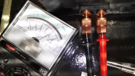
My reason for the pic of the probes touching each other was just to show that the meter was reasonably calibrated. I just fine tuned the cal and the readings, while not an absolute short on two of the three input connection screws and binding posts, match exactly on both channels. And again the, less than absolute short, readings on the binding posts exactly match the binding post readings on the other two amps. I'm quite sure everything is as it should be. I'll bet if I took the covers off the other two amps, and checked the comparable two input connections, I would get the same readings as the Mod86. It's time to bundle and tie wrap the wires.
Two resistance measurements that I recommend.
Speaker Return Terminal to Chassis.
Input RCA/Phono barrel to Chassis.
Then disconnect the Safety connection from Main Audio Ground to Chassis and recheck those two measurements.
The first two should read near zero ohms.
The last two should read near infinity.
Do not disconnect the Safety connection PE wire to Chassis. This must remain permanently attached.
I read the posts about twisting wires and Tom's response. I'm not going to twist them. I will just tie wrap them such that each group is in tight intimate contact.
That doesn't include the long wires from the transformer to the AC inlet. I question if the long, black and red, wires should just be bundled together and tie wrapped or would it be better to twist the red and black together such that it ends up as one grouping of four twisted wires?
Thanks
henry
That doesn't include the long wires from the transformer to the AC inlet. I question if the long, black and red, wires should just be bundled together and tie wrapped or would it be better to twist the red and black together such that it ends up as one grouping of four twisted wires?
Thanks
henry
Just a warning about using the Molex crimper with TE Connectivity fastons. In an earlier post I mentioned the crimper didn't work with the TE fastons. However I did get two TE fastons strongly secured to the wires by crimping, rotating the faston and crimping again. After about four crimps I thought I had a good connection and a strong pull test didn't move the wires. When I tried to put them on the terminals they would not lock on. They were clearly distorted by the repetitive crimping with the Molex tool.
Now that I bought some Molex faston type quick connects everything works perfectly.
Now that I bought some Molex faston type quick connects everything works perfectly.
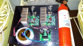
You know... I really recommend the Pyrochem brand of fire extinguishers. They just sound so much better. The Kidde brand that you have is OK, but I find it lacking in the highs and the midrange is tinny and whimsical. 🙂
Looks good. That stiffener on the bottom turned out well.
Tom
Looks good. That stiffener on the bottom turned out well.
Tom
Ya, I wear ear plugs when I use it. The brace is square steel channel 1/2" X 1/2" x 1/16" wall thickness. There is no flexing.
I just found an interesting product and would like to know if anyone's tried it.
MG Chemicals Extreme Conductivity Silver Epoxy for Cold Solder
Cat.No. 8330-20g
Volume Resistivity 0.0006 ohm – cm
Hardness 83D
Operating temp range -40C to 150C
Compression Strength 5199 PSI
Tensile Strength 12.9 MPa
MG Chemicals Extreme Conductivity Silver Epoxy for Cold Solder
Cat.No. 8330-20g
Volume Resistivity 0.0006 ohm – cm
Hardness 83D
Operating temp range -40C to 150C
Compression Strength 5199 PSI
Tensile Strength 12.9 MPa
Even better than a two-bolt clamping bar is a bar with a center screw.Either way is overkill but a clamping bar across the package makes sense if you're aiming for overkill. Jeff Rowland does that in his LM3886 amp.
Tom
Like this, except... a little different: HardwareLogic: Reviews - Zalman CNPS9500 AT CPU Cooler
Puts the clamping load pressure where it should be, and not on the edges.
Just a heads-up. I bought a TE Connectivity AC inlet module, for the Mod 86, from Mouser and it was defective out of the box. The heads-up is really to keep receipts until you try things...maybe even for the length of the warranty. On simple things, like an AC module, I usually toss the receipts, which I thought I had done. I called Mouser and they said I didn't buy it from them and, not having a receipt, I couldn't prove it. Hours later I found it, called them back, gave them the purchase number and they shipped me a replacement. Lesson learned is I'm keeping receipts for almost everything I buy.
I thought so but they told me, when I first called and didn't have the receipt, that they never sold the item to me. Maybe they didn't look hard enough.
When I called them back, after finding the receipt, at first they said the didn't see the purchase. After I gave them the receipt info they found it immediately. All I know is I'm glad I found the receipt. I was using the back for scribbling notes.
When I called them back, after finding the receipt, at first they said the didn't see the purchase. After I gave them the receipt info they found it immediately. All I know is I'm glad I found the receipt. I was using the back for scribbling notes.
As BrianL said, if you ordered online, you can get all the invoices from your previous orders in your order history. I do that all the time as part of my business bookkeeping.
Tom
Tom
- Home
- Amplifiers
- Chip Amps
- Modulus-86 build thread