It does seem like a small solidly made device. I wonder why Aavid-Thermalloy make so many variations of clips designed to apply clamping force on the main body of semi-conductor packages. Are they also into snake oil salesmanship?
I've observed that my Adcom and Mccormack get barley warm to the touch, while my Aragon 8008BB could probably qualify as a small room heater.
I'm going to use the Mod86 see where it falls in relation those amps. If it is like the Adcom or Mccormack I won't make any clips.
OMG Dude!
You are your own worst enemy...I've been building amps using these exact chips for like fifteen years, guess what, I've never used anything but the single screw into the heat sink on any of them and I have never had any thermal issues. In fact, none of the amps I've built have the chips themselves ever gotten hot as measured by direct temperature probe to the chip itself, nor do the heat sinks get any more than moderately warm.
Put those things together already and enjoy then.
Mike
You can always go through the math and calculate the heat sink temperature under typical and worst case conditions. You can find the math here: LM3886 chip power amplifier thermal design.
ModuShop gives you the thermal resistance of the heat sinks used in their chassis. You can measure the supply voltage in your amp. On the Thermal Design page, I give you all the necessary math to figure out the rest.
Tom
ModuShop gives you the thermal resistance of the heat sinks used in their chassis. You can measure the supply voltage in your amp. On the Thermal Design page, I give you all the necessary math to figure out the rest.
Tom
Last edited:
Just wondered why Aavid clips
I just thought Aavid might have a valid reason for selling spring clips for packages with mounting holes
As I said I'm going to start listening. It is already fully assembled.OMG Dude!
Put those things together already and enjoy then.
Mike
I just thought Aavid might have a valid reason for selling spring clips for packages with mounting holes
The reason is that it makes assembly faster and more reliable (= cheaper).
The TO-220 package has been around since around the time dirt was invented. Why should the rest of the world remove the hole in the TO-220 package, making it incompatible with older circuits that use the mounting hole, just because Aavid comes out with a fancy clip? These packages tend to be somewhat regulated by JEDEC. Removing the mounting hole from the TO-220 would require the package number to change. So now Aavid would have to either change the clip so only the new package would fit or leave the clip as-is and having it be compatible with both the TO-220 and the new package. The latter option would be better for marketing. "Our clip supports both the classic TO-220 and the newfangled TO-220-sans-hole".
Rather than creating problems by over-thinking things, how about spending the time until your soldering iron arrives reading a book, solving Soduko puzzles, or something? Just a suggestion... Give yourself a break.
Tom
Last edited:
A really good book to read is "The Art of Electronics" - many of us grew up with the second edition which was in print for over 25 years, but the third edition came out last year. Here's a thread on it with posts from one of the authors:
http://www.diyaudio.com/forums/lounge/268729-art-electronics-3rd-ed-april-2015-a.html
http://www.diyaudio.com/forums/lounge/268729-art-electronics-3rd-ed-april-2015-a.html

measurement confusion
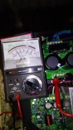
When I put probes on pwr86 J1 clamp screws for wires 5 & 6 I get 24V and 24V for 7 & 8. Based on that I believe the transformer is doing what it should.
When I tested J2 I put one probe on GND and the other on a +28V screw and get 14V. See the photos. What am I doing wrong or not understanding?
Thanks,
henry
Attachments
When I put probes on pwr86 J1 clamp screws for wires 5 & 6 I get 24V and 24V for 7 & 8. Based on that I believe the transformer is doing what it should.
When I tested J2 I put one probe on GND and the other on a +28V screw and get 14V. See the photos. What am I doing wrong or not understanding?
Thanks,
henry
Try measuring across "+" terminal and "-" terminal.
When I put probes on pwr86 J1 clamp screws for wires 5 & 6 I get 24V and 24V for 7 & 8. Based on that I believe the transformer is doing what it should.
When I tested J2 I put one probe on GND and the other on a +28V screw and get 14V. See the photos. What am I doing wrong or not understanding?
The two (+) terminals are connected to the same voltage. As are the two (-) terminals. If you measure the correct voltage on one (+) terminal and a different voltage on the other (+) terminal, you either aren't making good contact with the probe tip (the most like the cause) or the terminal block or the terminal block has a cold solder joint.
Given that you bough the boards preassembled and tested by me, odds are 99.99999 % in favour of the probe tip not making a good connection. Try measuring at J3 of the amp modules.
Tom
A really good book to read is "The Art of Electronics" - many of us grew up with the second edition which was in print for over 25 years, but the third edition came out last year. Here's a thread on it with posts from one of the authors:
http://www.diyaudio.com/forums/lounge/268729-art-electronics-3rd-ed-april-2015-a.html
That's a good suggestion, actually. Henry, I second the suggestion of adding this book to your reading list. You can find the table of contents here: Table of Contents | The Art of Electronics 3rd Edition
Tom
what can happen
What was the result of using the meter's probes, with the meter set to measure resistance, with the circuit on?From what I saw, the readings are probably fine. They're several ohms higher than the absolute short you show with the probes touching each other, and a high power circuit will likely measure something like that with the power off.
Also, you should NOT try to measure RESISTANCE when the circuit is on! You might know this already, but it can be easy to forget. Don't ask how I know.
What was the result of using the meter's probes, with the meter set to measure resistance, with the circuit on?
An ohmmeter works by applying a known test current to the resistance under test and measuring the voltage drop across the resistance. To answer your question, ask yourself what would happen if you drove a, say, 1 mA test current into the various accessible nodes on the Modulus-86. You should also ask yourself what would happen if the test current caused the amplifier to fight back, given that the amp is capable of producing voltages significantly greater than a typical ohmmeter can handle. Further, I also suggest you ask whether the answer is relevant to the build of the Modulus-86 or whether it would be better served if asked in a separate thread, for example in the Tools & Equipment forum.
Tom
What was the result of using the meter's probes, with the meter set to measure resistance, with the circuit on?
If you try to measure voltage with the meter set for resistance the best case scenario is a blown fuse in the meter, next best case is a blown meter that's repairable, worst case is a blown meter not worth repairing. 😡
Mike
While I was testing voltage values, with the amp plugged in and on the 5A slow blow fuse blew. I might have had one of the meters set to resistance by mistake.
I was using either a Micronta analog or a Velleman digital when the fuse blew. I just tested both to determine if they got damaged. Both meters are accurate for AC, at a 120V outlet and a 9V and 1.5V battery. Both also tested accurate for resistance.
I put in a new fuse and things normal. What could have caused the fuse to blow?
Also the reading at J1 with probes at connections 1 & 4 is 50VAC. Reading with probes at either 1 & 2 OR 3 & 4 are 25VAC.
Readings at J2 with probes at 1 & 6 and 2 & 5 are both 66VDC. Readings with probes at 1 or 2 & 3 and 4 & 5 or 6 are 33VDC. Reading at J3 with probes at V+ & V- is 66V and with probes at GND & V+ or GND & V- is 33V. There are no xlr or speaker cables connected. Do these readings seem reasonable?
Thanks,
henry
Last edited:
Blowing a mains fuse while probing = No Bueno!!
Links are focused on HV tube gear, but please, please don't mess around and get hurt
Electrical Safety | Tubelab
http://www.diyaudio.com/forums/tubes-valves/30172-safety-practices-general-ultra-high-voltage.html
Links are focused on HV tube gear, but please, please don't mess around and get hurt
Electrical Safety | Tubelab
http://www.diyaudio.com/forums/tubes-valves/30172-safety-practices-general-ultra-high-voltage.html
While I was testing voltage values, with the amp plugged in and on the 5A slow blow fuse blew. I might have had one of the meters set to resistance by mistake.
Dang!
I put in a new fuse and things normal. What could have caused the fuse to blow?
My guess is that a probe slipped and caused a short circuit. Second guess would be that you had the meter set to measure current.
Also the reading at J1 with probes at connections 1 & 4 is 50VAC. Reading with probes at either 1 & 2 OR 3 & 4 are 25VAC.
Readings at J2 with probes at 1 & 6 and 2 & 5 are both 66VDC. Readings with probes at 1 or 2 & 3 and 4 & 5 or 6 are 33VDC.
Sounds reasonable for a Power-86 powered by an Antek AS-2222 or AS-3222.
Reading at J3 with probes at V+ & V- is 66V and with probes at GND & V+ or GND & V- is 33V. There are no xlr or speaker cables connected. Do these readings seem reasonable?
Yep. J3 on the MOD86 should measure those values at no load when using a Power-86 and an Antek AS-2222/AS-3222 transformer.
Also check the DC offset on the output of the amp. Should be well below 1 mV (mine check in at 45 µV).
Tom
Blowing a mains fuse while probing = No Bueno!!
Links are focused on HV tube gear, but please, please don't mess around and get hurt
Electrical Safety | Tubelab
http://www.diyaudio.com/forums/tubes-valves/30172-safety-practices-general-ultra-high-voltage.html
Thanks for posting those. Yeah, with high voltage you only get one chance. There are several threads in the Tubes forum about near-death experiences and such resulting from electric shock.
Tom
I didn't realize, right away, that the fuse blew. Not even sure what meter I was using or what the probes were touching.
I just decided to check the duplex wall outlet and the found the receptacle for the round grounding pin, on a three pin cord, is not connected to ground.
I know I was testing some of the connections for voltage with one probe on the earth ground lug screwed to the case bottom. I'm thinking that, since there was no path to ground, that may have caused the fuse to blow. Maybe I didn't have the meter set incorrectly.
While testing I was trying to remember to turn of the amp off every time I was checking resistance.
I removed the outlet and found old two wire BX cable clamped to the back of the box. The BX and box have excellent conductivity. Unfortunately the other end of the BX, where ever it is, is not connected to ground at the electrical panel.
This wiring was done a long time ago and there are 32 lines going into the panel. For now I'm putting in a two pin duplex. about 15 years ago I checked all outlets and used two pin outlets where appropriate. I missed the one in the one story wing. Fortunately, when I had an electrician mount electric baseboard heat, in that room, I also had him install a properly grounded three pin duplex. All this was done on an opposite wall, so the old one was never checked.
I'll change the outlet if I can get the BX connected to ground. It's a very old house and still has some post and knob lines spliced to two wire BX in several places. The work was probably done over well 60 years ago.
Do install a GFCI receptacle at the end of the BX and for that matter your other 2 pin receptacles. There are smaller GFCI receptacles designed to fit in the older, smaller outlet boxes.
About 20 or 25 years ago I checked all the wiring throughout the house and installed GFCIs in outdoor outles. All kitchen, bathroom and darkroom outlets have GFCI circuit breakers in the main panel and I test them all about once a month.
My machine shop is wired to code, including the proper clearance around a second power panel for the 220V equipment. Clearly I missed that one outlet in the one story wing.It was behind a piece of furniture and was used for a lamp. Since it was a three pin duplex I thought is was OK because the other outlets were properly wired.
Big lesson learned...don't assume anything.
.
- Home
- Amplifiers
- Chip Amps
- Modulus-86 build thread