It's alive!
Good news of the day: It looks like we'll get the LME49710NA (8-pin DIP) back as well as a couple of the other LME-line ICs.
The full note of pardon is here: (.pdf)
A screen shot of the important bits is attached.
I'm not planning any changes to the Modulus-86 as a result of this. I'll stick with the TO-99 can. It performs very well. Ain't broken. Don't fix it. 🙂
DIP availability does make life easier for those who have yet to populate their Rev. 2.0 boards.
Tom
Attachments


Ok! Now work on getting the LM4780 back in the game!
Yeah... Good luck with that one. Broad market part in an expensive package. I think the business case will be thrown back in your face with a big bold [REJECTED] across the front. I do like the thought, though.
I have not given up on getting two LM3886es to play nicely, though. In many ways I prefer that over a single LM4780. Mounting two LM3886TFs on a heat sink is pretty easy. Mounting an LM4780 on a heat sink is pretty annoying, actually. To date, I've found exactly one thermal pad that'll fit the LM4780 package. Then you add the whole mess with clamping bars and such and you start wishing you'd used two LM3886es. 🙂
My hope is hinging on a circuit like two MOD86es in parallel. I'll see about getting that running in the lab this afternoon.
Tom
PS: Thanks to twest820 for forwarding to me the PCN from TI with the parts being brought back to life.
Last edited:
You must eliminate all air from the interface.
That is the sole purpose of the thermal goop.
This exactly. Even if the surfaces are exquisitely flat, all we've succeeded in doing is reducing the amount of thermal compound needed to fill the in gaps (as the rms roughness has gone down).
Yeah... Good luck with that one. Broad market part in an expensive package. I think the business case will be thrown back in your face with a big bold [REJECTED] across the front. I do like the thought, though.
I have not given up on getting two LM3886es to play nicely, though. In many ways I prefer that over a single LM4780. Mounting two LM3886TFs on a heat sink is pretty easy. Mounting an LM4780 on a heat sink is pretty annoying, actually. To date, I've found exactly one thermal pad that'll fit the LM4780 package. Then you add the whole mess with clamping bars and such and you start wishing you'd used two LM3886es. 🙂
My hope is hinging on a circuit like two MOD86es in parallel. I'll see about getting that running in the lab this afternoon.
Tom
PS: Thanks to twest820 for forwarding to me the PCN from TI with the parts being brought back to life.
Indeed. FWIW, on my Parallel-86 builds, I purchased numerous Bergquist Silpads and MAXCLIP08g's...
Best,
Anand.
How do these get fitted?Indeed. FWIW, on my Parallel-86 builds, I purchased numerous Bergquist Silpads and MAXCLIP08g's...
Best,
Anand.
place the clip over the device and hole and then screw in the bolt?
or
screw on the clip and then lift and push the device under?
The clips I have are made of pretty stiff spring steel. I'd place the clip over the device and then drive a machine screw through the hole in the clip.
There are some heat sinks out there (small ones) that offer a lever action clamp. They're a bit expensive, but man they're convenient. Especially for TO-220 packages. Just drape a SilPad sleeve over the device and flip the lever and you have the correct mounting pressure right on the centre of the device. I like it. Sadly, these heat sinks are not suitable for audio amps at LM3886 power levels. They might work well for a headphone amp.
Tom
So I'm having a little fun in the lab...
As promised, I decided to see what kind of performance one could get by coupling two channels of Modulus-86 in parallel. It turns out, quite good performance, actually.
In The Good Old Days™, i.e. the days of the Modulus-86 Rev. 1.0, putting two channels of MOD86 in parallel was supported on the board. It was a modular amp, hence, the Modulus name. Nobody seemed to build them that way, however, and the ballasting resistor needed for parallel operation does add directly to the output impedance, so in Rev. 2.0 and beyond, I took that option off the menu and pointed people to the Parallel-86 instead. Now with the LM4780 being obsolete, I found myself mulling over what would happen when two channels of MOD86 are put in parallel.
I used my 4-channel Modulus-86 Rev. 2.0 amp for this test. I connected a 0.1 Ω, ±1 %, 3 W resistor from the (+) output of each channel to a common point, the new speaker (+) output. I connected the two output grounds together to the new speaker (-) output. The resulting performance plots are attached. I didn't do a full test suite on this, but the initial results certainly look promising.
For those looking to build a MOD86 with two channels in parallel, I suggest the following:
Tom
As promised, I decided to see what kind of performance one could get by coupling two channels of Modulus-86 in parallel. It turns out, quite good performance, actually.
In The Good Old Days™, i.e. the days of the Modulus-86 Rev. 1.0, putting two channels of MOD86 in parallel was supported on the board. It was a modular amp, hence, the Modulus name. Nobody seemed to build them that way, however, and the ballasting resistor needed for parallel operation does add directly to the output impedance, so in Rev. 2.0 and beyond, I took that option off the menu and pointed people to the Parallel-86 instead. Now with the LM4780 being obsolete, I found myself mulling over what would happen when two channels of MOD86 are put in parallel.
I used my 4-channel Modulus-86 Rev. 2.0 amp for this test. I connected a 0.1 Ω, ±1 %, 3 W resistor from the (+) output of each channel to a common point, the new speaker (+) output. I connected the two output grounds together to the new speaker (-) output. The resulting performance plots are attached. I didn't do a full test suite on this, but the initial results certainly look promising.
For those looking to build a MOD86 with two channels in parallel, I suggest the following:
- Change R12 and R13 to ±0.1 % tolerance types.
- Instead of the Thiele network, populate one 0.1 Ω, 3 W, ±1 % tolerance resistor (metal film preferred) in the spot for R5. I used Mouser P/N: 66-LOB3R100FLF.
- Move the Thiele network (L1, R5) to the Speaker (+) output terminal.
- Connect the outputs of the two MOD86 channels in parallel to the output connector and Thiele network with matched wire lengths between the two channels.
Tom
Attachments
-
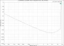 2 x MOD86 Rev. 2.0 in Parallel_ THD+N vs Output Power (4 ohm, 1 kHz, 20 kHz BW).png45.7 KB · Views: 283
 -
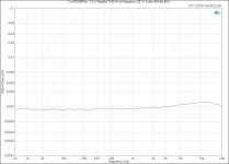 2 x MOD86 Rev. 2.0 in Parallel_ THD+N vs Frequency (32 W, 4 ohm, 60 kHz BW).PNG26.4 KB · Views: 285
 -
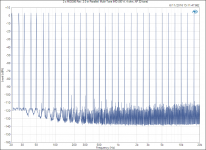 2 x MOD86 Rev. 2.0 in Parallel_ Multi-Tone IMD (80 W, 4 ohm, AP 32-tone).png77.2 KB · Views: 280
Last edited:
It seems they didn't scrap all the worn out plant they had used for these special ICs.
Yeah. Many, me included, didn't buy the official story of a fab closure. My guess is that they moved the processes to newer equipment and needed to make new masks to fit the new equipment. At that point it's pretty reasonable to evaluate which products to migrate and which to obsolete. Mask sets are not cheap.
That's my guess anyway.
Tom
In The Good Old Days™, i.e. the days of the Modulus-86 Rev. 1.0, putting two channels of MOD86 in parallel was supported on the board. It was a modular amp, hence, the Modulus name. Nobody seemed to build them that way, however,
Some of us are really slow with our projects OK 😛
Good to know performance is good, in case I do need the higher current delivery.
Yep. Apply the Rev. 1.0 -> 2.0 component tweaks and connect your Rev. 1.0 boards in parallel and you should get the performance I measured earlier today.
The power supply in my 4xMOD86 amp is an Antek Inc. AS-3222 (2 x 22 VAC, 300 VA) with a single Power-86 board, by the way.
Tom
The power supply in my 4xMOD86 amp is an Antek Inc. AS-3222 (2 x 22 VAC, 300 VA) with a single Power-86 board, by the way.
Tom
lm3886 mounting thoughts
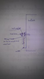
I noticed the lm3886tf has a step on the front surface. It is thinner were the screw goes through and thicker at the lower body section. I have a feeling the thicker section is where the “goods” are embedded. Is that true? If so this makes me think the clamping force of a washer and screw is not at the appropriate location.
The clamping force should be over the area were the embedded, working, heat generating stuff is located. Using a washer and screw, in the existing hole, just won't apply any significant pressure on the larger thicker section below the mounting hole.
If the “goods” are really embedded in the thicker section, I will make a clamp as shown below or maybe just mill a, large diameter, thick washer. That would be easiest since heatsinks are already tapped at proper locations. Another option would be to use a piece of strip stock as a clamp. It would only need a hole at each end, span the lm3886 and be secured to the heatsink via two drilled and tapped holes in the heatsink. Either way may be considered overkill but am I missing something?
Attachments
Sanity prevails. 🙂
Tom
Maybe not, but I still have a huge grin on my face right now- it's groundhog day!!
Maybe not, but I still have a huge grin on my face right now- it's groundhog day!!
ROFL! I know the feeling...
 🙂
🙂I noticed the lm3886tf has a step on the front surface. It is thinner were the screw goes through and thicker at the lower body section. I have a feeling the thicker section is where the “goods” are embedded. Is that true?
See BrianL's comment earlier.
If so this makes me think the clamping force of a washer and screw is not at the appropriate location.
National/TI's packaging group would have fixed the package if there was an issue.
Another option would be to use a piece of strip stock as a clamp. It would only need a hole at each end, span the lm3886 and be secured to the heatsink via two drilled and tapped holes in the heatsink. Either way may be considered overkill but am I missing something?
Either way is overkill but a clamping bar across the package makes sense if you're aiming for overkill. Jeff Rowland does that in his LM3886 amp.

As I said, it's way overkill but it does look pretty and makes for good marketing copy.
Tom
Okay so maybe I'm wasting my time. However if the idea of using the goop is to eliminate air gaps how can one possibly know if this was accomplished? If surfaces are not perfectly flat and clamping force is not optimized how can one possibly know if they have the optimal contact or a thick layer of goop. That wouldn't be known unless clipping or stripping heat sensors occurs. It seems, to me, that improving clamping is very easy and cheap and can provide some confidence that the best contact with the least amount of goop has been achieved. All the science and then one of the last steps is, well maybe it's OK.
Just saw the pic of the Rowland chip clamping. That is what I was trying to describe but not as fancy. Makes sense to me if the workings are in the thicker part of the chip.
Henry, just get on with it. The advanced technology of using the provided screw hole has been proven just fine for a good 50 years now. I'm not sure what you're trying to prove by overly anal-izing every simple step. It's not going to make a ---- bit of difference in the result.
It's been 30+ years since my last Thermo course, but my hunch is the "low hanging heat transfer fruit" lies on the cold side of he heat sink rather than at the interface. (simple steps to assure good air flow etc)
Tom - I do want that sharp looking Dale resistor in the Roland amp PCB photo - can you please design something with that component?
Tom - I do want that sharp looking Dale resistor in the Roland amp PCB photo - can you please design something with that component?
- Home
- Amplifiers
- Chip Amps
- Modulus-86 build thread