I will, however, post some pics as the build moves forward.
Awesome. Thanks Henry. I'm looking forward to seeing your progress. With your machining capabilities you should be able to do amazing things.
Tom
Based on responses, to my posts, there doesn't seem to be a need for any cleverly machined chip clamps or anything else...seems its all been done before.
All the pics will show are, your components, a bunch of wire, off the shelf connectors and a case made in Italy. Nothing exciting. However I'm expecting the sound to be exciting.
I just need to get a new soldering station to finish it. I tested mine, for the the third time, last night and its time to toss it. At full power it takes a very long time to get a 14awg wire hot enough to tin it. And that was with a brand new chisel tip.
Henry, exactly my point. There has been little new in the world of 'standard' heat-sinking in a good 50 years. The "ON Semi" app-note that Tom dug up is, in fact, a very old Motorola app-note that was 'rebranded' when ON was split off from Motorola.
Tom has a very good section on his web site (and in the construction manuals) about choosing heat sinks.
First of all, Tom, I'm not looking for a response from you. You have already done a great job with your instructions and responses, to my"beginners" posts, which have been very enlightening.
Brian, I just want to mention that there are at least two drawings, in the ON-SEMI pdf, that show the package curled or raised slightly off the heatsink surface. The example is the single screw mount, through the hole in the tab, LM3886 type. That is exactly why I was concerned before ever seeing the drawings. The design just struck me as something that could allow the main body to raise up, especially, after heating and cooling cycles. It is why I thought making a simple clamp, that would apply pressure on the main body, would be a good thing. I may still machine two for my stereo Mod86.
Long term use impressions
Have been playing my build for about 18 months now and thought one individual's day to day experience with the amp could possibly be of interest to someone on the fence for building one. I have early V1.0 PCB's purchased in late 2014 and know there are tweaks and improvements since then.
Some thoughts:
The sound is very, very good, "clean" might be a single word description. (sorry, not feeling any audio-spew verbiage at the moment so will spare everyone any attempt at that)
Well documented straightforward to build.
It's a bargain - I am hard pressed to imagine doing better at anywhere near this cost or even multiples of the cost. (full disclosure - Mod86 is in my rack next to some expensive tube gear. They're both wonderful and I feel fortunate and perfectly happy listening to either amp, but if one needs great sound at reasonable cost it's no contest)
Reliable - have had zero issues or fussing.
Runs very cool, room temp almost (I did use oversize heat sinks, 10" x 3.25")
I play a lot of vinyl and quite like the Mod paired with my tube phono stage.
It punches above its weight for power rating and have had good success pushing speakers I normally play with 100 WPC amps.
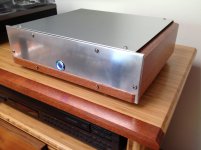
Initially posted impressions about a year ago. Everything has proven really solid and this is a massive thread so re-attaching photo of my scratch build enclosure and layout that (minus the wood bits, those were difficult to integrate) was really pretty simple to fabricate: Used two 10" Heat Sink USA pieces as side frames then drilled, tapped and bolted on some 3/4" angle stock front and back then added panels. As stated above, very happy with thermal management and am convinced oversize heat sink was good choice for long term durability.
Outside the heat sinks I think it was maybe $20 for aluminum from the local sheet metal place and some fussing with drills and taps.
It's a great product - thanks Tom
Have been playing my build for about 18 months now and thought one individual's day to day experience with the amp could possibly be of interest to someone on the fence for building one. I have early V1.0 PCB's purchased in late 2014 and know there are tweaks and improvements since then.
Some thoughts:
The sound is very, very good, "clean" might be a single word description. (sorry, not feeling any audio-spew verbiage at the moment so will spare everyone any attempt at that)
Well documented straightforward to build.
It's a bargain - I am hard pressed to imagine doing better at anywhere near this cost or even multiples of the cost. (full disclosure - Mod86 is in my rack next to some expensive tube gear. They're both wonderful and I feel fortunate and perfectly happy listening to either amp, but if one needs great sound at reasonable cost it's no contest)
Reliable - have had zero issues or fussing.
Runs very cool, room temp almost (I did use oversize heat sinks, 10" x 3.25")
I play a lot of vinyl and quite like the Mod paired with my tube phono stage.
It punches above its weight for power rating and have had good success pushing speakers I normally play with 100 WPC amps.
Initially posted impressions about a year ago. Everything has proven really solid and this is a massive thread so re-attaching photo of my scratch build enclosure and layout that (minus the wood bits, those were difficult to integrate) was really pretty simple to fabricate: Used two 10" Heat Sink USA pieces as side frames then drilled, tapped and bolted on some 3/4" angle stock front and back then added panels. As stated above, very happy with thermal management and am convinced oversize heat sink was good choice for long term durability.
Outside the heat sinks I think it was maybe $20 for aluminum from the local sheet metal place and some fussing with drills and taps.
It's a great product - thanks Tom
Attachments
Last edited:

Just buy a couple of the large transistor clamps at Digikey and be done with it - the 2 screw flat bars can press unevenly on the package unless you're using tensioning washers and/or a torque driver - Fischer have a wide variety of these clips like the THFM1 or the THFM10 - curved spring clips are better but, it's a tedious job looking for them
I was going to make the clamp such that it would be attached with one screw going through the hole in the tab. It would apply pressure on the both the tab and, the thicker portion of the body, below the tab. I have a few spring washers that would allow fairly even pressure at both locations. I happen to have a bunch of thin scraps of sheet titanium, from a previous job, that should work real well. I love finding uses for scraps of expensive materials. Can't bring myself to throw that stuff away.
Last edited:


Looking lovely, Henry.
I've used the Hakko plenty, never the Metcal. With a good tip (factory) the Hakko is pretty darn good.
I've used the Hakko plenty, never the Metcal. With a good tip (factory) the Hakko is pretty darn good.
Henry,
Get a Hakko 936 and don't look back. Mine has been working for years and the product is well supported.
Best,
Anand.
Get a Hakko 936 and don't look back. Mine has been working for years and the product is well supported.
Best,
Anand.
I happen to have a bunch of thin scraps of sheet titanium, from a previous job, that should work real well. I love finding uses for scraps of expensive materials. Can't bring myself to throw that stuff away.
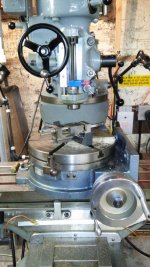
My milling machine is set up for small parts so the time is right for making Ti clamps.
Attachments
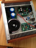
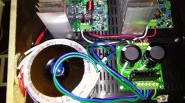
Here are latest pics with some wiring completed. Can't solder since my station is dead. Should I get a good condition Metcal or a new Hakko?
You really should twist those wire pairs and triples together, it will help minimize stray reactance's and EMI.
Like this:

Mike
Last edited:
Thanks for the advice. However I had planned to never pull the wiring unless something went wrong with the power supply or PCBs. Could I just strip a foot of shielding from some old cable I have and wrap it around the wires?
I don't think it'll be too terrible to unscrew the wire clamps on one side and at least just twist the wires per bundle.
The right is too short...would need new wires. The left side might allow two turns. I'd much rather use shielding I have. I love using stuff lying around instead of tossing it.
The sound is very, very good, "clean" might be a single word description. (sorry, not feeling any audio-spew verbiage at the moment so will spare everyone any attempt at that)
[...]
Well documented straightforward to build.
[...]
It's a bargain - I am hard pressed to imagine doing better at anywhere near this cost or even multiples of the cost.
[...]
It's a great product - thanks Tom
Awesome. Thank you. I really appreciate your feedback. Sorry for chopping up your post there. I enjoyed reading all of it.
Tom
The right is too short...would need new wires. The left side might allow two turns. I'd much rather use shielding I have. I love using stuff lying around instead of tossing it.
I wouldn't worry too much about twisting the wires. Do keep them tightly coupled (so tightly bundled with cable ties) but don't obsess too much over twisting the wires. Unless you get a really tight twist, you'll likely do more harm than good by twisting the wires. Also you need to get both the VCC and VEE coupled tightly to ground. That's nearly impossible in a 3-conductor twist.
Unless your shielding material is thicker than 10 mm, don't bother. The skin depth at 20 Hz is over 10 mm in copper. You'll get no meaningful attenuation unless you use material that's at least one skin depth thick.
The most important wires to keep tightly coupled are the wires coming out of the transformer (both primary and secondary). That's where the charging currents for the main supply capacitors flow. Those currents are short pulses, so if anything couples to the rest of the circuit, it would be those. The currents from the Power-86 to the Modulus-86 boards is averaged quite a bit by the supply caps on the Modulus-86 boards.
Tom
Henry, yes I've seen that very exaggerated drawing in the Motorola ap-note. Of course, the warp of the tab doesn't have to be that much to compromise the thermal performance. Still, that is largely hypothetical. I've NEVER had a TO-220 - style package that wasn't flat.
If you find you are compelled to clamp, rather than machine your own clamp, consider something like the Aavid MAX07NG or MAX08NG
If you find you are compelled to clamp, rather than machine your own clamp, consider something like the Aavid MAX07NG or MAX08NG
Other chip manufacturers also show this as a potential failing.................
Brian, I just want to mention that there are at least two drawings, in the ON-SEMI pdf, that show the package curled or raised slightly off the heatsink surface. The example is the single screw mount, through the hole in the tab, LM3886 type. That is exactly why I was concerned before ever seeing the drawings. The design just struck me as something that could allow the main body to raise up, especially, after heating and cooling cycles. It is why I thought making a simple clamp, that would apply pressure on the main body, would be a good thing.............
I don't like your stepped clamp. But a stepped clamp that sits on the heatsink and has a strong & stiff tongue that clamps down on the main body would be OK. Still using the hole through the device for the main bolt. Needs a really strong thread attachment since half the load is onto the heatsink and the other half is the clamping force.
I agree.You really should twist those wire pairs and triples together, it will help minimize stray reactance's and EMI.
Like this: View attachment 554762
Mike
Twist EVERY Flow and Return Pair. Mains, Speaker, Signal, Power.
I don't agree with Tomchr on this ( and I don't have any numbers to prove my contention)
one (1) twist per 2" (50mm) is better than no twists. You don't need 4 twists per inch to get good averaging of the fields for good attenuation of emi.I wouldn't worry too much about twisting the wires. Do keep them tightly coupled (so tightly bundled with cable ties) but don't obsess too much over twisting the wires. Unless you get a really tight twist, you'll likely do more harm than good by twisting the wires. Also you need to get both the VCC and VEE coupled tightly to ground. That's nearly impossible in a 3-conductor twist.
Cat5 uses tight twisting because the pairs are in contact with each other AND it is designed for >100MHz signaling.
Last edited:
- Home
- Amplifiers
- Chip Amps
- Modulus-86 build thread