It's the new science they are teaching our kids at school, except Scotland. We still rely on teaching real science
It's the new science they are teaching our kids at school, except Scotland. We still rely on teaching real science
It's just calculus Scotland is failing at! (sorry couldn't resist).
Brain fart. I see what you were saying about the V+/- wire lengths. Good catch.
Tomchr had mentioned earlier about using microphone cable for the XLR signal wiring (which I am going to do). This gave me the idea to hack up an IEC power cable and use that for wiring the V+/gnd/V-. It seems like that will keep it nice, twisted, and tidy with a minimal amount of manipulation.
Edit: heck, the Mogami mic cable seems like it would be just fine for the V+/gnd/V- wiring as well in this instance.
I've used old computer IEC power cords before, black, white and green per twisted is very convenient, not to mention those cords seem very plentiful.
I can't remember where I (I think) read that Tom likes 12AWG, but then tom used 13 just because he had some around. I did use old IEC cord on my preamp/dac, but I think it was only 16 or 18 guage. With the amplifier it may be more important to have bigger stuff.
I have some mic-cord I got from Redco Audio. I plan to get some 6-conductor / 13 gauge wire for speakers (I'm tri-amping a 3 way loudspeaker), and use speakon connectors. I was thinking of hacking a small length of the speaker cable for power too, not sure yet.
Some years ago I got a couple feet of some really small (22 awg or 26 awg) solid core silver wire, with a braided silk sheath. I don't care about the sheath, but I like it for input signal. I think it's very low resistance, very low capacitance, allows line level signals to travel very fast. I'm not a big believer in ferry dust on cables, but I guess I drank the coolaid on that one. It was cheap though. 😛
I had conveniently forgotten about that already.It's just calculus Scotland is failing at! (sorry couldn't resist).
This is me just thinking aloud, no facts to back this up:...........................Some years ago I got a couple feet of some really small (22 awg or 26 awg) solid core silver wire, with a braided silk sheath. I don't care about the sheath, but I like it for input signal. I think it's very low resistance, very low capacitance, allows line level signals to travel very fast. I'm not a big believer in ferry dust on cables, but I guess I drank the coolaid on that one. It was cheap though. 😛
woven silk thread will have a high proportion of air in the weave and in the thread.
That air content, like foamed dielectric and air cell dielectric of coax, will reduce the dielectric of the insulation to an average value somewhat nearer to an air spaced wire pair.
That should have a performance effect and that effect is probably measurable.
I've used old computer IEC power cords before, black, white and green per twisted is very convenient, not to mention those cords seem very plentiful.
I can't remember where I (I think) read that Tom likes 12AWG, but then tom used 13 just because he had some around. I did use old IEC cord on my preamp/dac, but I think it was only 16 or 18 guage. With the amplifier it may be more important to have bigger stuff.
I have some mic-cord I got from Redco Audio. I plan to get some 6-conductor / 13 gauge wire for speakers (I'm tri-amping a 3 way loudspeaker), and use speakon connectors. I was thinking of hacking a small length of the speaker cable for power too, not sure yet.
Some years ago I got a couple feet of some really small (22 awg or 26 awg) solid core silver wire, with a braided silk sheath. I don't care about the sheath, but I like it for input signal. I think it's very low resistance, very low capacitance, allows line level signals to travel very fast. I'm not a big believer in ferry dust on cables, but I guess I drank the coolaid on that one. It was cheap though. 😛
I use the #24 awg solid core used in network cables for lots of wiring because of skin depth, they generally result in clean sound. If I need thicker cables, for example speaker internal wiring, I just use more strands for more current. This gives flexibility to optimize cable thickness and strand count.
If everyone was so honest DIY Audio would be a better place. 🙂I have absolutely no science in my brain to show if this would be beneficial. .....Sorry, I don't think I'm helping
The short answer to your cable length question is it doesn't matter; one reason I gave Tom the general circuit used in the Modulus is I wanted DIYers to have ready access to high enough CMRR and PSRR for supply and ground related errors to be negligible.
The longer answer, to summarize earlier explanation in this thread and the Mod vendor's bazaar thread, is minimum error residuals correlate well with minimum supply impedance. So shorter wiring is better; there's no problem taking the optimization you're considering. With amps of lower CMRR and PSRR balancing wiring lengths for a stereo pair of channels can be meaningful in manipulating the relative difference between them, at least to the extent left and right signals tend to be highly correlated. Whether this is better than minimizing absolute error is a sufficiently complicated psychoacoustic topic it was rather less work to design to make errors introduced by reasonable wiring practice negligible. In that sense, recent discussion of wiring type here is irrelevant; to summarize the maths posted earlier AWG16 or larger twisted pair or braid is plenty good. At least barring silly things like going round the chassis 10 times.
This appears to be an assertion the impedance term in Ohm's law enjoys some form of privilege over voltage or current terms. You'll need to be more specific for me to see what you're on about as, mathematically, this is trivially not the case.This will not be effective as an argument point, because it is not effective.
It seems better to ask a question instead.
You know how the purpose of the typical Thiele Small Amplifier Output Filter (specifically, all 4 components--both the RC and the inductor||resistor, all installed properly) is to defeat the need of custom speaker cable. So, my question is: Will the same thing work for the DC umbilical cable?
You know how the purpose of the typical Thiele Small Amplifier Output Filter (specifically, all 4 components--both the RC and the inductor||resistor, all installed properly) is to defeat the need of custom speaker cable. So, my question is: Will the same thing work for the DC umbilical cable?
Assemble the amplifier first and get it working properly.
Good advice if the builder is assembling the MOD86 as his first project ever. For someone with good soldering skills, there's no reason they shouldn't build it up in one shot. That's what I did with my build. I did power it up gently using a fused variac on the first power-up. I also used sockets for the DIP ICs so I could verify the on-board low-noise regulators before plugging everything in.
I normally wouldn't advise a "big bang" test, but with the level of documentation I deliver, you're very likely to be successful on the first try. That's what I deliver. Confidence.
Get the grounding sorted so that it plays with two input channels connected and no ground loops.
If you assemble the boards and connect them as shown in the supplied project documentation, there's really nothing to sort out. Just connect the dots and go.
Once the bare amp is tested and playing properly, fold it up into the shape it will need to be in to fit the proposed chassis. test again that the new locations of the components have not interfered with the good performance.
Unless you have test gear on hand, you're not likely to be able to determine that.
Then buy a Chassis that fits around the final tested and working layout.
Or assemble the boards, measure their dimensions, and pick a chassis that'll work. In a well-designed amplifier, such as the Modulus-86 and any other amplifier I offer, the chassis or layout should have no impact on the performance of the circuit.
Tom
I've used old computer IEC power cords before, black, white and green per twisted is very convenient, not to mention those cords seem very plentiful.
Many of those are 16 AWG. Some skinnier than that. The heavy duty ones, that you probably don't want to cut up, are 14 AWG.
For the supply connections, I used 16 AWG. It would have been nice to go a little heavier, mostly for looks, as the amp performs to spec. as-is.
On the output, I used some 12 AWG (I think) zip cord. Worked pretty well.
On the input, I chopped up an XLR microphone cable. If you do the same, just make sure to tame the shield. I strip about 15 mm of the outer jacket, unbraid the shield, and twist it into a single conductor. I then apply heat shrink to the single conductor and a larger diameter piece that covers the outer jacket and a little of where the conductors emerge from the jacket. I've been using that method for years and it's quite reliable and neat.
I can't remember where I (I think) read that Tom likes 12AWG, but then tom used 13 just because he had some around. I did use old IEC cord on my preamp/dac, but I think it was only 16 or 18 guage. With the amplifier it may be more important to have bigger stuff.
Some years ago I got a couple feet of some really small (22 awg or 26 awg) solid core silver wire, with a braided silk sheath. I don't care about the sheath, but I like it for input signal. I think it's very low resistance, very low capacitance, allows line level signals to travel very fast. I'm not a big believer in ferry dust on cables, but I guess I drank the coolaid on that one. It was cheap though. 😛
You're right about the fairy dust and Kool-Aid. 🙂 But hey... Each to his own. I've seen more issues in builds with fancy skinny wire than in builds that use regular UL1007 spec. copper wire.
Tom
The short answer to your cable length question is it doesn't matter; one reason I gave Tom the general circuit used in the Modulus is I wanted DIYers to have ready access to high enough CMRR and PSRR for supply and ground related errors to be negligible.
Point well made. It's the composite amplifier topology of the Modulus-86 that causes the high performance level. This is well-documented in the literature and the composite amplifier topology has been used for decades in precision applications. The real design work in the Modulus-86 was to make the composite topology work nicely with the LM3886 and its quirks. Optimizing the layout and measuring the performance of different PCB layout iterations was another fun little excursion. 🙂 Furthermore, a significant chunk of work went into designing the circuit such that it could be produced at higher volume with a good success rate, even when assembled by relatively inexperienced DIYers.
Good circuits are well-designed, well-tested, and well-documented. That's what I deliver.
Tom
Thiele+Zobel combinations address other design issues. Thieles (L||R) are an audio optimized form of RISO compensation, the most common method of improving amplifier stability into capacitive loads. Zobels (R+C) provide a resistive alternative to inductive loads such as dynamic drivers above audio frequencies and sometimes offer mitigation of LC resonances from cables' RLCG or other sources.Will the same thing work for the DC umbilical cable?
Tim Green's series on amp stability is a good starting point if you want to know more about compensation methods.
Ayup; I particularly enjoyed the layout parasitic and IMD workbacks on the Mod's performance limits. 🙂Optimizing the layout and measuring the performance of different PCB layout iterations was another fun little excursion.
Last edited:

Hi 12B4A,
That looks very good, can I ask how you created the large cutout for the power socket? I have a similar case and would like to incorporate a fused socket.
Thanks, Ian
That looks very good, can I ask how you created the large cutout for the power socket? I have a similar case and would like to incorporate a fused socket.
Thanks, Ian
I drilled many holes and used a fine blade coping saw to cut between the holes to make one large hole. I then used a high speed Dremel cutting bit (#196) to smooth out the sides. It wasn't a quick and elegant process at all. I'm pretty sure next time I'm going to see if I can get that kind of cutout properly cnc'ed.
Thanks, that's sort of how I was thinking of doing it but I was hoping you had a neat trick or tool for the job.🙂
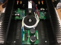
Reached a small milestone of sorts. All the metal work is done and everything fits together. There's still more to do electrically but it's a good day when the drill gets put away.
I suggest reversing the position of the xformer and rectifier board. First of all, you go from dirty to clean in a proper layout. Xformer is dirtiest. Perhaps even more important is that you want as short as possible distance between the reservoir caps and the amp pcb. Inductance is your fiend.
You might consider picking up the drill again.
Get a nibbling tool Amazon.com: nibbling toola neat trick or tool for the job.🙂
My Adel nibbler has got to be 40 years old and still works fine. Paid for itself ten times over (or maybe a hundred, especially considering the price of custom punches).
The Original Adel Nibbling Tool
I drilled many holes and used a fine blade coping saw to cut between the holes to make one large hole.
That's one approach. I usually drill a hole in each corner of the square outline and saw between them using a coping saw. I then use a file to flatten the sides and get the hole to its final dimension. Having access to a milling machine would be nice, but for the one hole per year that I need to make that way, the cut-n-file method works just fine.
For larger round holes, such as those for XLR connectors, I use a stepped drill. Works great, and unlike large HSS drills, there're no issues with the drill bit wandering creating a hexagonal hole.
Get a nibbling tool
Works great for thin sheet goods. For the 3 mm thick aluminum in the chassis I used, I doubt it'll work so well.
Tom
- Home
- Amplifiers
- Chip Amps
- Modulus-86 build thread