One thing I do notice is that the LM3886es aren't mounted on the heat sinks. They just lean against them. You have to drive a screw through the mounting hole in the IC package into the heat sink.
The sinks are drilled and trapped. Anticipating a problem, I didn't apply compound or screw to the sinks for the final check.
In an older revision of the Design Documentation there was a typo on the pin number. If you measure on the socket for the OPA2277, you need to measure on pin 4 and pin 8. If you measure on the sockets for the LME49710 or the THAT1200, you need to measure on pin 4 and 7. You should still get ±15 V.
OK, I get +15V on pin 8.
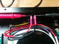
Would you measure the voltage at the amplifier output connector?
I'm getting from 5 to 7 mV on each amp.
it possible that the black or white wire insulation on one side is preventing contact with the screws in the green terminal blocks
This concerned me initially, but as long as the wire is not stripped too short, the terminal block will not permit this to happen.
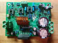
Attached, my take on a bulb tester and a closeup of a board.
Attachments
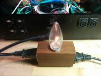
That bulb filament is glowing more than dimly.
Why?
Whatever mistake I've made, I seem to have faithfuly repeated it 4 times.
The sinks are drilled and trapped. Anticipating a problem, I didn't apply compound or screw to the sinks for the final check.
OK, I get +15V on pin 8.
I'm getting from 5 to 7 mV on each amp.
This concerned me initially, but as long as the wire is not stripped too short, the terminal block will not permit this to happen.
Attached, my take on a bulb tester and a closeup of a board.
What's the watt rating of the bulb in your tester? It could be too low for the combined idle current draw of the circuits. If so, the glow would be normal.
Mike
Last edited:
What's the watt rating of the bulb in your tester? It could be too low for the combined idle current draw of the circuits. If so, the glow would be normal.
Mike
I started with a 150 W and moved down to 25 W. No glow at 60 W.
Last edited:
I started with a 150 W and moved down to 25 W. No glow at 60 W.
A dim glow from a 25W bulb implies just a few watts drawn, so you're probably OK there.
Regarding having the 3886 chips just resting against the heat sinks instead of attaching is a bad idea. Even at idle there could be enough heat generated to cause problems. I recommend that you at least use a screw to hold the chip against the heat sink while testing. For final assembly, use a good heat sink compound (not too thick, thin film works best) for the most efficient heat transfer.
Mike
There is no way that the amps can be drawing enough current to droop the supply like that without something smoking. Look at the voltage at the transformer primary . . .
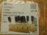
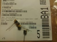
Comparing my boards to the photo at the top of the design doc, all caps seem to be oriented properly, but Mouser has clearly sent me different parts for C1 and C17, and C3. I am trusting they are equivalent. Photos attached.
My diodes all appear to be oriented properly.
C31 and C27 is the same part in bill of materials, but the markings on the caps I received are slightly different. I have 4 with 408 SEPF 22 35 and 4 with 509 SEPF 22 35 (I made two orders at Mouser)
The voltage regulators are oriented properly and have not been switched, but I don't supposed I would have got good measurements at pins 4 and 7/8 if they had been.
With a 150 W bulb get a full 120 V at the primary and +-33 V at each amp! Have I misunderstood how to use the bulb tester? Have I wired the tester incorrectly?
My diodes all appear to be oriented properly.
C31 and C27 is the same part in bill of materials, but the markings on the caps I received are slightly different. I have 4 with 408 SEPF 22 35 and 4 with 509 SEPF 22 35 (I made two orders at Mouser)
The voltage regulators are oriented properly and have not been switched, but I don't supposed I would have got good measurements at pins 4 and 7/8 if they had been.
Do you mean like this (photo)? I get 80 V with a 25 W bulb and 112 V with a 60 W bulb.Look at the voltage at the transformer primary
With a 150 W bulb get a full 120 V at the primary and +-33 V at each amp! Have I misunderstood how to use the bulb tester? Have I wired the tester incorrectly?
Attachments
And now the LM4780 is reaching the same fate...
LM4780TA/NOPB Texas Instruments | Mouser
LM4780TA/NOPB Texas Instruments | Integrated Circuits (ICs) | DigiKey
https://www.rocelec.com/parts/results/all/?s=LM4780TA/NOPB
LM4780TA/NOPB - TEXAS INSTRUMENTS - Audio Power Amplifier, AB, 2, 60 W, 20V to 84V, TO-220, 27 | Newark element14
Do we need to do a group buy or something?
I need 8 of them!
Thanks,
Anand.
I use the same transformer in my 4-channel build.
Was it an AS-3222 or an AS-3224 like mine? Antek was out of stock on the 22 when I ordered. I've powered up without my bulb tester and am getting a full +-35V with four amps connected, exactly the same as with none connected. I was expecting it to fall to within the 20 - 28 V range. Is +-35 V too high? Must I change R9, 20 and 22 now?
With ICs socketed I now read +-34.5V with no DBT.
Time to quit for today. Here in Montreal it has yet to snow and is well above freezing. Hard to get into the holiday spirit and it looks like no shinny rinks for a week or two at least.
Happy holidays everyone!
Time to quit for today. Here in Montreal it has yet to snow and is well above freezing. Hard to get into the holiday spirit and it looks like no shinny rinks for a week or two at least.
Happy holidays everyone!
Look's like there's no solder on the second pin from the right on LM3886 in the photo.
Steve.
Steve.
Is +-35 V too high?
I asked a similar question about transformer size. See Tom's reply here: http://www.diyaudio.com/forums/vend...r-achieving-0-0004-thd-n-178.html#post4388414
The questions now are: are your speakers 4ohm or 8ohm? Are your heat sinks adequate?
I read through the heat sink section of Taming LM3886 on Toms site several times, then I figured out how to write the formulas from there into Microsoft Excel. It really helped me to feel confident in my heat sink choice when I could prove it with math.
Happy Holidays!
A dim glow from a 25W bulb implies just a few watts drawn, so you're probably OK there.
Regarding having the 3886 chips just resting against the heat sinks instead of attaching is a bad idea. Even at idle there could be enough heat generated to cause problems. I recommend that you at least use a screw to hold the chip against the heat sink while testing. For final assembly, use a good heat sink compound (not too thick, thin film works best) for the most efficient heat transfer.
Mike
There is no way that the amps can be drawing enough current to droop the supply like that without something smoking. Look at the voltage at the transformer primary . . .
How many times Do I and others need to say it?Comparing my boards to the photo at the top of the design doc, all caps seem to be oriented properly, but Mouser has clearly sent me different parts for C1 and C17, and C3. I am trusting they are equivalent. Photos attached.
My diodes all appear to be oriented properly.
C31 and C27 is the same part in bill of materials, but the markings on the caps I received are slightly different. I have 4 with 408 SEPF 22 35 and 4 with 509 SEPF 22 35 (I made two orders at Mouser)
The voltage regulators are oriented properly and have not been switched, but I don't supposed I would have got good measurements at pins 4 and 7/8 if they had been.
Do you mean like this (photo)? I get 80 V with a 25 W bulb and 112 V with a 60 W bulb.
With a 150 W bulb get a full 120 V at the primary and +-33 V at each amp! Have I misunderstood how to use the bulb tester? Have I wired the tester incorrectly?
The Mains Bulb Tester is a way to avoid damaging equipment at first Power ON whenever a new or modified project needs to be first powered.
It allows one to find out if there are any wiring errors and eliminate them.
Michael and Dewa are asking the question to discover if you are asking the Mains Bulb Tester to do something it was NEVER intended to do !
The Mains Bulb Tester is NOT for normal operation.
National have the spreadsheet for a large part of their power chipamp range.I asked a similar question about transformer size. See Tom's reply here: http://www.diyaudio.com/forums/vend...r-achieving-0-0004-thd-n-178.html#post4388414
The questions now are: are your speakers 4ohm or 8ohm? Are your heat sinks adequate?
I read through the heat sink section of Taming LM3886 on Toms site several times, then I figured out how to write the formulas from there into Microsoft Excel. It really helped me to feel confident in my heat sink choice when I could prove it with math.
Happy Holidays!
It is worth searching for. It is linked regularly on this Forum.
According to Tom's documentation, if your normal operation power supply voltage ends up north of 28V you would just have to change R9 to 47.5k for the power up un-muting to work smoothly. ~34 volts is about right for the transformer you selected going to a cap-loaded FWB rectifier. Your mains voltage might also be a little higher than 115 which also gives you a higher than anticipated power supply voltage.
I'm curious to know what you guys with the Modulus and LXminis have to say about the combination.
I'm curious to know what you guys with the Modulus and LXminis have to say about the combination.
The Mains Bulb Tester is NOT for normal operation.
The "Final Check" section of the design doc specifies two tests, one verifying the voltage has been properly regulated on the IC sockets, and the other testing the DC offset on the output of the amp. The doc recommends are current-limited power supply for each test.
My mistake was assuming I could measure the voltage on the input of the amp in the same context. It is clear to me, now that I think about it, that when the bulb is small it will significantly reduce the voltage supplied to the amp.
Thanks for the help.
Look's like there's no solder on the second pin from the right on LM3886 in the photo.
The LM3886 was soldered from underneath. The solder you see on the other pins was drawn through the holes. In retrospect, I would have off lifting the IC several millimetres above the board before soldering. Excess solder drawn through the holes of the back pins could bridge to an adjacent pin the way the way I did it. It also makes it more difficult to acurately mark the centre of the hole on the heatsink because the tops of the coils of the Thiele network get in the way. Too late for me now, I've clipped the pins.
According to Tom's documentation, if your normal operation power supply voltage ends up north of 28V you would just have to change R9 to 47.5k
It's not super critical to change the MUTE resistor. I'd say if the amp works as-is, leave it. If you're getting thumps on start-up or shut-down, change R9. With the higher supply voltage, the IC will come out of mute a bit sooner. Not the end of the world, really.
I'm curious to know what you guys with the Modulus and LXminis have to say about the combination.
I'm quite happy with my 4xMOD86 + LXmini. The people who have listened to my setup have been quite impressed as well.
Tom
OK, I get +15V on pin 8.
Cool. The onboard regulators are working then.
I'm getting from 5 to 7 mV on each amp.
Sounds like the LM3886 is doing its job as well. Life is good. Plug in the DIP ICs and give it a go. Do make sure that the mains inlet is fused, though.
Comparing my boards to the photo at the top of the design doc, all caps seem to be oriented properly, but Mouser has clearly sent me different parts for C1 and C17, and C3. I am trusting they are equivalent. Photos attached.
It happens at times that Mouser runs out of parts or that a capacitor goes end-of-life. In those cases, I chose an equivalent or better part and update the project BOM with Mouser.
My diodes all appear to be oriented properly.
I looked at the diodes and U5, U6 in your pictures. I can't see anything wrong there either.
C31 and C27 is the same part in bill of materials, but the markings on the caps I received are slightly different. I have 4 with 408 SEPF 22 35 and 4 with 509 SEPF 22 35 (I made two orders at Mouser)
As long as they're both 22 uF, 35 V caps and fit in the board, life is good.
And now the LM4780 is reaching the same fate...
Newark has 62 in stock. Electronic Components Distributor Newark element14
Tom
- Home
- Amplifiers
- Chip Amps
- Modulus-86 build thread