Does anyone know how these connectors on a Neutrik NC3FD-LX-BAG are intended to be soldered? There is an inner metal cup and an outer inverted u-shape metal part which looks like it's intended to be crimped. Am I supposed to strip the wire to the depth of both parts (about 8mm) or just to the depth of the inner cup? In other words, is the outer part intended to crimp the insulation, or to crimp the bare wire just to hold the it in place while its being soldered?
Attachments

Instructions are on Neutrik website for EMC XLRs
This is apparently intended to be crimped, and there seems to be contact and a special tool needed.
The Neutrik XLR is the EMC line, and the full part is NC3FD-LX-HA-BAG. I tried to attach the pdf but the Forum will not allow it, so you need to go to the Neutrik US website and download it from there.
In a production environment, you'd crimp the contacts to the wire then shove it into the connector housing. That's my guess.
In a DIY environment, however, you're free to just solder it and call it good.
Tom
In a DIY environment, however, you're free to just solder it and call it good.
Tom
This is apparently intended to be crimped, and there seems to be contact and a special tool needed.
The Neutrik XLR is the EMC line, and the full part is NC3FD-LX-HA-BAG. I tried to attach the pdf but the Forum will not allow it, so you need to go to the Neutrik US website and download it from there.
The Neutrik datasheet specifies the wiring as "solder contacts". The crimps seem too light to be the only means of connection. My guess is they are intended to temporarily hold the wire in place as it's being soldered.
Last edited:
Here's the web link, relevant PDF is on the right side of the page. NC3FD-LX-HA-BAG - Neutrik
You are right, I was shipped the HA model. Not having a b-crimper, I have soldered. Thanks.
I have soldered. Thanks.
Hey SnowyEgret, are you listening yet? How do you like it? I ordered mine just the other day.
Hi AlexQS,
Completed my build a few days back. Initial impressions are positive. 🙂 At the risk of sounding cliched, if you are looking for a transparent, neutral sound, the Mod-86 will not disappoint.
Completed my build a few days back. Initial impressions are positive. 🙂 At the risk of sounding cliched, if you are looking for a transparent, neutral sound, the Mod-86 will not disappoint.
Last edited:
Oh good. I've heard nothing but positive. I'm getting excited because my tweeters are 104dB efficient, as you can imagine they reproduce any noise in my system, and I'm excited because I'll finally have an amp clean enough to handle them quietly. Cheers!
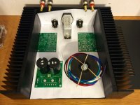
My build is starting to take shape but I would appreciate any constructive feedback before I start drilling. I went with the B3209A chassis from along. I had a different layout in mind before I had all the parts on hand but once they arrived I quickly discovered I'd have to move the PS board and xfmr.
Attachments

That's pretty much layout my build ended up with (see post 698). Only really a few possibilities with basically four sub assemblies to move around.
Assemble the amplifier first and get it working properly.
Get the grounding sorted so that it plays with two input channels connected and no ground loops.
Once the bare amp is tested and playing properly, fold it up into the shape it will need to be in to fit the proposed chassis. test again that the new locations of the components have not interfered with the good performance.
Then buy a Chassis that fits around the final tested and working layout.
I've been studying Toms layout on page 89 of this thread, as I plan my build.
In looking at the pictures about 2 posts up from here (sorry OP, firgot yer name already) I see a couple things you may not have considered: 1 is that if you rotate the Power86 90 degrees you might be able to keep it on the center line, but I'm not even sure if that's important. The other thing I see is that in your other picture, with the trafo and power86 side-by-side, if you swap the two components, then the wire runs from the power86 to each mod86 will be closer to equal in length of wire, again I'm not sure if this is important. AndrewT helped me years ago by telling me to twist all my pairs of wires, I've found through trial and Andrew helping me to fix the error that having wires neat and tidy with zip-ties and all is in fact important, although I bet Tom's circuit is more resilient anyway.
In looking at the pictures about 2 posts up from here (sorry OP, firgot yer name already) I see a couple things you may not have considered: 1 is that if you rotate the Power86 90 degrees you might be able to keep it on the center line, but I'm not even sure if that's important. The other thing I see is that in your other picture, with the trafo and power86 side-by-side, if you swap the two components, then the wire runs from the power86 to each mod86 will be closer to equal in length of wire, again I'm not sure if this is important. AndrewT helped me years ago by telling me to twist all my pairs of wires, I've found through trial and Andrew helping me to fix the error that having wires neat and tidy with zip-ties and all is in fact important, although I bet Tom's circuit is more resilient anyway.
In looking at the pictures about 2 posts up from here (sorry OP, firgot yer name already) I see a couple things you may not have considered: 1 is that if you rotate the Power86 90 degrees you might be able to keep it on the center line, but I'm not even sure if that's important. The other thing I see is that in your other picture, with the trafo and power86 side-by-side, if you swap the two components, then the wire runs from the power86 to each mod86 will be closer to equal in length of wire, again I'm not sure if this is important. AndrewT helped me years ago by telling me to twist all my pairs of wires, I've found through trial and Andrew helping me to fix the error that having wires neat and tidy with zip-ties and all is in fact important, although I bet Tom's circuit is more resilient anyway.
These are some good comments. That would work rotating the power86 to keep the transformer mounted center-ish. My speculation there is that it would be beneficial to shorten the wire lengths between the power outlet to the xfmr and then to the P86 board while also keeping the rectification further away from the signal section.
I'm not sure what you mean with the side-by-side swapping suggestion since it seems that would just lengthen one end while equally shortening the other.
Yes, you're right, it's all a trade off.
What I meant is that on the mod86 board, if I'm seeing it right, the wire run from power86 would be an inch or so to the left board. However on the right channel the V+\- is on the other end of the amp board, so that wire run will be at least a few inches longer. Please don't think I know what I'm talking about, but I'm just saying that if the power 86 board is in front of the right side, then the wire run will be a few inches toward the back to the far side of that board, and also a few inches across to the left channel which has it's v+\- on the closer to the front of the amp. It just makes sense to me, given the option to have those power leads more similar in length, but I have absolutely no science in my brain to show if this would be beneficial. .....Sorry, I don't think I'm helping
What I meant is that on the mod86 board, if I'm seeing it right, the wire run from power86 would be an inch or so to the left board. However on the right channel the V+\- is on the other end of the amp board, so that wire run will be at least a few inches longer. Please don't think I know what I'm talking about, but I'm just saying that if the power 86 board is in front of the right side, then the wire run will be a few inches toward the back to the far side of that board, and also a few inches across to the left channel which has it's v+\- on the closer to the front of the amp. It just makes sense to me, given the option to have those power leads more similar in length, but I have absolutely no science in my brain to show if this would be beneficial. .....Sorry, I don't think I'm helping
My speculation there is that it would be beneficial to shorten the wire lengths between the power outlet to the xfmr and then to the P86 board while also keeping the rectification further away from the signal section.
I forgot to say, your idea above sounds smart to me. Then again I think that a lot of this doesn't really matter. Tom put so much hum-rejection and other things into the design of the board that I probably won't notice much any sonic differences in my choice of layout, long as I follow common sense.
I hope you'll post more pictures as you make progress. 🙂
Brain fart. I see what you were saying about the V+/- wire lengths. Good catch.
Tomchr had mentioned earlier about using microphone cable for the XLR signal wiring (which I am going to do). This gave me the idea to hack up an IEC power cable and use that for wiring the V+/gnd/V-. It seems like that will keep it nice, twisted, and tidy with a minimal amount of manipulation.
Edit: heck, the Mogami mic cable seems like it would be just fine for the V+/gnd/V- wiring as well in this instance.
Last edited:
At the output of the power board, for that and all other audio connections inside the chassis, I would advise the simplicity of solid conductor copper wire.
For example, if your multi-strand cable has 12 corrosion resistant coated conductors and if you use that from power board to amplifier board, then your speaker level signal has to transverse 12 different paths, causing up to 12 slightly different copies, before it is overlain onto the DC supply, which is what happens to your speaker level signal directly before it is available for your speaker to use. It isn't even as well as that in practice. Multi-strand cable is patchwork--the many conductors don't go unbroken throughout the entire length, but instead the fibers vary in length. It is the insulation and twist, pushing the different length fibers together that maintains conductivity. Think of it as a bit of patchwork. Likewise, whichever fiber didn't go unbroken the entire length will have a slightly different signal at endpoint. That is a blur. And it may get confusing as well as a partial excuse for selling custom audiophile cables. Those expensive custom cables can't do better than fix a problem that you shouldn't have installed anyway.
So, when it comes to getting signals to go intact over very short distances, I think that you should choose the simplicity of a solid conductor cable that has one unbroken conductor throughout the entire length. These can be spiral twisted, not braided, not knotted, not woven, not knitted and absolutely never crocheted. 😀
Daniel,
Since litz wire is specifically used for very high frequencies, and since litz wire consists of many individually isolated strands, there must be something wrong with your line of reasoning. Actually, there is a lot wrong with it.
The concept of '12 different paths' causing '12 slightly different copies' is incorrect. Google litze wire or skin effect.
The many conductors do go unbroken throughout the entire length of a cable. Otherwise, it is broken.
Upshot: there is no electrical reason to use any kind of specific cable for audio use, as long as it is thick enough to carry the current.
For me, solid conductor copper wire only works comfortably up to fairly small diameter. Multi strand is the easiest for connection of sub-assemblies within a device. It is also the most reliable. Larger diameter solid core wire can put stresses on the terminals which are best avoided.
For example, if your multi-strand cable has 12 corrosion resistant coated conductors and if you use that from power board to amplifier board, then your speaker level signal has to transverse 12 different paths, causing up to 12 slightly different copies, before it is overlain onto the DC supply, which is what happens to your speaker level signal directly before it is available for your speaker to use.
Granting that this is true, those different copies are, at worst, moving at 50% the speed of light at a distance of less than foot. I find it implausible that it would have an audible effect. There are more practically valid reasons to use solid core such as less chance of errant frays causing shorts and it holds bends easier which helps with routing.
- Home
- Amplifiers
- Chip Amps
- Modulus-86 build thread