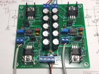
The PCB for the 2-channel amplifier has gone together fine, so here are the latest schematic and gerbers.
I have some amp PCBs that I can send out too, £1.50 each + postage.
I also have another batch of sinewave PCBs available (a tweaked version with easier R3 placement for the 3rd phase).
I have some amp PCBs that I can send out too, £1.50 each + postage.
I also have another batch of sinewave PCBs available (a tweaked version with easier R3 placement for the 3rd phase).
Attachments
Last edited:
It's back, thankfully, as that would have affected quite a few of my projectsStill waiting on the PRO version to become available...
Thanks - here's the re-posted #87:
I've made a fairly major update to the firmware of this project, to support some new options and features.
It can now support an SSD1306 based 128x64 OLED display as an alternative to the Bluetooth/RemoteXY interface:

(Re-)Added a 'reference' signal output that can be looped back into the TACH input for testing/debugging (as is being used in the pictures above).
A new 'soft-start' feature which ramps the amplitude up over ~2s:

Although I've reduced the computational load of the sinewave generation to ensure the buttons and display remain nice and responsive, spectral purity of the full-amplitude sinewave is still good:

I've got a bit of tidying up of the firmware to do, then devise a neat solution for connection of the display (probably using extended headers on the required pins), after which I'll update the design information for this updated version.
- Richard
I've made a fairly major update to the firmware of this project, to support some new options and features.
It can now support an SSD1306 based 128x64 OLED display as an alternative to the Bluetooth/RemoteXY interface:
(Re-)Added a 'reference' signal output that can be looped back into the TACH input for testing/debugging (as is being used in the pictures above).
A new 'soft-start' feature which ramps the amplitude up over ~2s:
Although I've reduced the computational load of the sinewave generation to ensure the buttons and display remain nice and responsive, spectral purity of the full-amplitude sinewave is still good:
I've got a bit of tidying up of the firmware to do, then devise a neat solution for connection of the display (probably using extended headers on the required pins), after which I'll update the design information for this updated version.
- Richard
Last edited by a moderator:
For 2 channel sine you can use one of these -
https://www.ebay.co.uk/itm/154713157434?hash=item24059f6f3a:g:aqIAAOSwALtaXV6s
Microstepping mode aka sine wave.
Includes programmable ramp up - ramp down and current limit.
https://www.ebay.co.uk/itm/154713157434?hash=item24059f6f3a:g:aqIAAOSwALtaXV6s
Microstepping mode aka sine wave.
Includes programmable ramp up - ramp down and current limit.
I used one of these DRV8825 PWM stepper motor micro-step drivers. Very efficient of both power and space, and you can run them backwards!
They are used to drive CNC and 3D printer motors.
https://www.ti.com/motor-drivers/stepper-driver/overview.html?keyMatch=STEPPER MOTOR DRIVER
https://www.ti.com/lit/ds/symlink/drv8825.pdf
They are available as modules, cheap.
https://www.pololu.com/product/2133
https://www.amazon.com/DRV8825-Step...hvlocphy=&hvtargid=pla-4584413744905264&psc=1
Last edited:

")
I'm happy with the update for the OLED display, so have updated the first post with the latest build guide which includes the OLED display option (also updated for the v1.1 boards), plus updated Gerbers.
For the firmware, please contact me directly so I can make sure you have the latest version.
New display:

Included in my testbed (this is set up to drive a Rega 24v motor directly from the original Rega PSU, using the amplifier board posted earlier in this thread):

For the firmware, please contact me directly so I can make sure you have the latest version.
New display:
Included in my testbed (this is set up to drive a Rega 24v motor directly from the original Rega PSU, using the amplifier board posted earlier in this thread):
Ah good. Yes you need to supply either 5v to the 5v pin, or 7-12v to the barrel jack for the onboard 5v regulator.Problem solved. My power supply to the Arduino was set for 5V which wasn't enough for the on board regulators to produce 5V on the board itself. Upped it to 9 v and all is well.
Every time the frequency or phase is adjusted, the value is saved to the non-volatile memory in the Arduino, so this should be happening already. Does this not appear to be happening for you?Is there any way to retain the settings (frequency especially) when power is lost?
- Home
- Source & Line
- Analogue Source
- 2 phase synthesised sinewave generator for synchronous motor drive