This is a shared DIY project for non-commercial use.
This project is an extension of the DIY Arduino tachometer; several users have requested a Nixie tube display as an alternate to the LCD. There are currently two versions of the Nixie display, using IN12 tubes and IN16. I've included the EagleWare .brd file if someone wants to modify it for use with other Nixie tube types.
The PCB uses all thru-hole components for easy assembly, but some soldering skills are still required. The uP is a DIP package but there is a socket for it on the board.
The project consists of a bare PCB, a parts "kit" available as a shared cart from Digikey electronics, a uP with the operating system pre-programmed into it and the on-line documentation you see here. The two PCBs are identical except for the display tubes, so the shared Digikey cart works for either build. It is highly recommended to use socket pins for mounting the IN12 tubes, which are not included in the Digikey shared cart. You must add them to your order. The Digikey PN for the pins is ED90326-ND; you will need at least 60 pcs (12 pins per tube). The IN16 tubes do not (and cannot) use sockets, they are soldered to the PCB.
The PCBs are available from OshPark PCB fabricators at the following links:
IN12: OSH Park ~
IN16: OSH Park ~
The PCB is created in multiples of 3 for a cost of ~$97.66 or $32.55/board.
The PCBs are available from PCBWay fabricators in China at the following links:
IN12: Nixie Tube Tachometer Display for IN12 type tubes - Share Project - PCBWay
IN16: Nixie Tube Tachometer Display for IN16 type tubes - Share Project - PCBWay
The PCB is created in multiples of 5 for a cost of ~$54 or $11/board.
The parts kit can be ordered from Digikey Electronics: Digi-Key - Fast Add
The parts kit to build 1 PCB costs $45.87. If you are using IN12 type Nixie tubes, it is highly recommended to add 60 pcs of ED90326-ND socket pins to make inserting and removing the tubes easier.
The pre-programmed uP is available in the US from DIYAudio member Seth Hensel via PM. Cost to US (shipping included): $13.
The pre-programmed uP is available in the EU and RotW from DIYAudio member Scobham via PM. Cost to UK (shipping included):£10. EU:£12.50 RotW: Depends on destination (Ask).
IN12 and IN16 Nixie tubes and the HV power supply are available from http://www.shop-tes.com. If ordering IN12 tubes, you must have at least one type IN12B which has a decimal point (middle tube on display); the other 4 can be IN12A (w/o decimal) or IN12B. There is only one version of the IN16 tube with decimal points. The HV power supply is type 1364 Horizontal.
The following documentation is available below to aid in construction of the project; the files are grouped into a zip file for each version (IN12.zip and IN16.zip) and a third file (Eagle.zip) has the necessary .brd, .lbr, & .cam files to modify the layout for other tube types.
INxx PCB.pdf
INxx Parts Locator.pdf
INxx Schematic.pdf
INxx BOM.pdf (Generic bill of materials with part references)
INxx Instructions.pdf
INxx Gerbers (folder with RS274X Gerber files if you want to use your own board house).
Eagle.zip (IN12 tach.brd, IN16 tach.brd, Nixie.lbr, IN12.DRL and NIXIE_IN12.cam Eagleware files to modify layout for other tube types).
Attachments
Last edited:
Do you think someone will be building the boards and selling them? I know it’s not for meant for this. But I’m disabled and it’s been getting pretty hard for me to do small board work the last two years
Thanks and great work and information
Thanks and great work and information
Example: I’m going to buy 3 PCBs and 2 of these will be going to sale for other our DYI members.
12B has has one decimal point (when 12A has numbers cathodes only). It is
implemented as lighted dot in lower part of tube.

12B has has one decimal point (when 12A has numbers cathodes only). It is
implemented as lighted dot in lower part of tube.
Do you think someone will be building the boards and selling them? I know it’s not for meant for this. But I’m disabled and it’s been getting pretty hard for me to do small board work the last two years
Thanks and great work and information
I can assemble one for you for free if you will order all requested parts.
I ordered PCBs from OSH Park and all parts from DigiKey. 2 PCBs can go to other DYI members (please PM me if interested). Will wait for programmed uP chip. Seth, please let me know when I can acquire it. Taylor Electronics has several HV PSU 1364 Horizontal units. Witch one is more appropriate?
Attachments
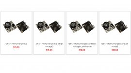
There only appear to be 2 versions of the HVPS, normal and low noise, even though they list 4. I ordered the first one.
My OSH Park PCB set is back from their Fab and will be shipped in next 48 hours to my home. Will have all parts in hands then, beside uP. Is any ETA available for pregamed uP be ready for shipment? I’ll be not be able to test it without it.
Sounds good. Thank you.
One more piece is missing in my BOM and it is HV PSU. It’s seems they are closed now due to quarantine. Nothing to do beside to wait...
One more piece is missing in my BOM and it is HV PSU. It’s seems they are closed now due to quarantine. Nothing to do beside to wait...
All is ready, beside uP. I’ll add a couple of my comments related to its assemble tomorrow. Can’t test it probably without the main chip....
Assembly went very smooth (very nice PCB design) and I got no any issues during soldering parts.
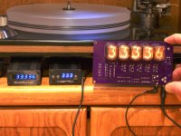
Tested it yesterday and it seems test mode is working fine. I'll upload some video to YouTube and add link to the thread.
Couple of remarks:
a. DigiKey Saved BOM has some extra pieces of varies parts. Not big deal and better to have inexpensive spares vs. missing pieces during assembly...
b. 3.5mm female connector for Tacho data is mirrored and I installed to the same side as all Tubes are connected.
c. I have very small part of some number cathode (somewhere inside) bit glowing on 2nd tube when I ran test on other tubes. I tested with two tubes at that position and both show (first more than the other) very small dot. No issue at all, but I feel that I need to report that.
Some questions:
a. Would be nice to add some simple drawing for TTL and RS232 signals going from Arduino UNO to Display to the manual.
b. I need Arduino Uno sketch (plan to use TTL) to run that display. Can you please share with yours?
c. BTW, can Arduino Uno be used with both displays same time? I mean to use LCD/OLED and in parallel to connect it to Nixie display…
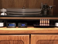
Bravo Pyramid!!! I have a lot of fun and like it. Very well made KIT and I’ll use it on my main TT (Wilson and Benesch Full Circle).
Tested it yesterday and it seems test mode is working fine. I'll upload some video to YouTube and add link to the thread.
Couple of remarks:
a. DigiKey Saved BOM has some extra pieces of varies parts. Not big deal and better to have inexpensive spares vs. missing pieces during assembly...
b. 3.5mm female connector for Tacho data is mirrored and I installed to the same side as all Tubes are connected.
c. I have very small part of some number cathode (somewhere inside) bit glowing on 2nd tube when I ran test on other tubes. I tested with two tubes at that position and both show (first more than the other) very small dot. No issue at all, but I feel that I need to report that.
Some questions:
a. Would be nice to add some simple drawing for TTL and RS232 signals going from Arduino UNO to Display to the manual.
b. I need Arduino Uno sketch (plan to use TTL) to run that display. Can you please share with yours?
c. BTW, can Arduino Uno be used with both displays same time? I mean to use LCD/OLED and in parallel to connect it to Nixie display…
Bravo Pyramid!!! I have a lot of fun and like it. Very well made KIT and I’ll use it on my main TT (Wilson and Benesch Full Circle).


Assembly went very smooth (very nice PCB design) and I got no any issues during soldering parts.
Tested it yesterday and it seems test mode is working fine. I'll upload some video to YouTube and add link to the thread.
Couple of remarks:
a. DigiKey Saved BOM has some extra pieces of varies parts. Not big deal and better to have inexpensive spares vs. missing pieces during assembly...
b. 3.5mm female connector for Tacho data is mirrored and I installed to the same side as all Tubes are connected.
c. I have very small part of some number cathode (somewhere inside) bit glowing on 2nd tube when I ran test on other tubes. I tested with two tubes at that position and both show (first more than the other) very small dot. No issue at all, but I feel that I need to report that.
Some questions:
a. Would be nice to add some simple drawing for TTL and RS232 signals going from Arduino UNO to Display to the manual.
b. I need Arduino Uno sketch (plan to use TTL) to run that display. Can you please share with yours?
c. BTW, can Arduino Uno be used with both displays same time? I mean to use LCD/OLED and in parallel to connect it to Nixie display…
Bravo Pyramid!!! I have a lot of fun and like it. Very well made KIT and I’ll use it on my main TT (Wilson and Benesch Full Circle).
Remarks:
a. Some of the parts require 5/6 pcs and it is cheaper to buy 10. For the single parts, I still listed 10 as they are inexpensive & it's good to have spares.
b. I changed the connector I used from the 1st prototypes to the final version and did not spin another PCB to test it. I either misread the datasheet for the new connector or it was mirrored (probably the former).
c. In lamp test mode, you should not have any other cathodes illuminated in other display tubes. This can happen in normal operation as the display is multiplexed and some leakage can occur. I purposely made the anode drivers push-pull to prevent this, but it is unavoidable in these types of displays. I could only see ghosts when looking at the display up-close.
Questions:
a. I can look at adding that, but updating the OP is a PITA wrt attachments. The instructions should be straight forward on how to make the connections.
b. The Arduino sketch on page 13 of the original thread has the needed code. The speed reading is sent to the serial port at 9600 baud in the correct format to be read by the Nixie display. The Arduino board outputs TTL unless you have an RS232 shield attached. Only 2 wires are needed: Gnd and TxD. The serial connector on the Nixie PCB is 3.5mm stereo (Tip/Ring/Shield or TRS). Gnd from Arduino goes to shield on Nixie; TxD goes to Ring. If your output is from a RR tach, just use a 3.5mm stereo M-M cable and plug it into the RR and the Nixie PCB; done.
c. You can use both displays at the same time. The LCD display can have averaging enabled, the serial port output to the Nixie tubes does not average the reading, so they may not always be the same (unless you disable averaging to the LCD). The LCD uses other digital pins for its display, the Nixie is attached to the serial port TxD.
About remarks:
Parts order logic is clear and personally like spares. My glow (as I mentioned, it is not big deal at all) is quite dull and barely visible. It is about 2-3 mm in size.
About questions:
Manual’s instructions are good enough for me, but some members might going to ask you for some graphical diagram. I do not see any sketch on page 13 (but each PC display might get different split for pages). I found sketch tach.txt on my screen page 14 (thread # 139). Hope this is the one. TRS is explained for TTL and for RS232 also clearly in your manual. I just wandered and needed your clarification about dual display usage. Lest see how averaging is differ vs. Nixie. Will report soon. Again, thank you a lot for exceptionally well created kit for us.
My mistake, it was page 14 and you are correct, post #139. Make sure to copy the .txt file; if you copy the code window, it randomly leaves off characters for some reason. You may have to download and install the display library for the LCD you use as well. I believe there is a discussion about this on the pages that follow.
Now, it wold be a challenge to make nice box for it. Some of you might know where to find front plate/panel that already got cut for IN-12 with such or aprox such spaces between them. Please share...

- Home
- Source & Line
- Analogue Source
- DIY Nixie Tube Display for turntable tachometer