I have a Nixie IN-12 board that passes self test. However, in RS232 mode and connected to a RR sensor mounted under a rotating platter with a magnet roughly 1mm from the sensor diode, all I get is the decimal point lit - none of the digits display.
I believe that the magnet might be ferrite rather than neo. With the magnet so close to the sensor, is this an issue?
Another potential culprit is that I had some trouble positioning the sensor (my first go at SMD soldering) and may have kept heat on the ground pin too long and/or too often.
Are there expected voltages at the jack(s) that I can check?
The IN12/16 is only a display, it is not a tachometer. You will need a RoadRunner tach or the Arduino tach project and use the Nixie display with that.
Finally, my tube sockets are arrived. 🙂 It took almost 3 month shipping time from Germany.
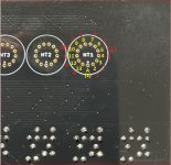
I tried to connect them via pint2point, but I'm totally mess-up with cathodes. Pyramid, can you please help me and mark VIAs on attached image with numbers?
That will make my assy way way easier. 🙂
I have IN-16 style PCB (BTW, I have many of these PCBs made in China Fab handy. Let me know if some of you interested..).
Attachments

Last edited:
I'm not sure what you are asking; are you using IN12 tubes (or some others) with an IN16 PCB?
If you are using IN16 tubes, align pin 1 of the tube (the only one with white insulation at the base inside the tube) with the index mark on the PCB (marked 'A' on you pic).
If you are using IN12 or other tubes with the PCB, pin 1 is the index mark and the pin numbers increase as you go CCW from there; the schematic shows which pin # controls which cathodes:
Pin #
1= Anode
2= Cathode 1
3= Cathode 7
4= Cathode 3
5= Cathode Left Dec Pt.
6= Cathode 4
7= Cathode 5
8= Cathode 6
9= Cathode 2
10= Cathode Right Dec Pt.
11= Cathode 8
12= Cathode 9
13= Cathode 0
Hi Pyramid,
Thank you a lot. This is exactly what I need.
Just for reminder, I'm using 7779 (B4032 BURROUGHS - the smallest Nexie ever made) with IN-16 sockets setup PCB. I updated my image with your info, so it will be easier for people who is using "remote" tubes on IN-16 PCBs.
Thank you a lot. This is exactly what I need.
Just for reminder, I'm using 7779 (B4032 BURROUGHS - the smallest Nexie ever made) with IN-16 sockets setup PCB. I updated my image with your info, so it will be easier for people who is using "remote" tubes on IN-16 PCBs.
Attachments
It worked out. All tubes dropped to sockets and connected trough wires based on the above diagram. Now I need to box all that together with Arduino. Hope, it will be one small box.
light up test failed
hi,
I have just finished my built, with IN12Bs, after long waiting for parts but:
There is no HT at HV PSU output (0 VDC)
Pin 1 and 2 of U3 sits on 0 VDC
Removing all the 3 ICs I get 170VDC on output pin of the PSU.
I have bought 3 uPs and tested with 2 of them so far, saving the third safely.
Please let me know how I should proceed avoiding the risk of destroying the HT PSU or the uP since it is hard to source them.
BTW thanks for sharing another excellent project.
BR
Periklis
hi,
I have just finished my built, with IN12Bs, after long waiting for parts but:
1.I have passed the 1st test (without the ICs)
2.Second test failed:
2.Second test failed:
a.ICs installed
b.Niexies installed
c.Jumper JP1 open
d.Jumper JP2 shorted
b.Niexies installed
c.Jumper JP1 open
d.Jumper JP2 shorted
There is no HT at HV PSU output (0 VDC)
Pin 1 and 2 of U3 sits on 0 VDC
Removing all the 3 ICs I get 170VDC on output pin of the PSU.
I have bought 3 uPs and tested with 2 of them so far, saving the third safely.
Please let me know how I should proceed avoiding the risk of destroying the HT PSU or the uP since it is hard to source them.
BTW thanks for sharing another excellent project.
BR
Periklis
If U3 is powered up, you should not have the same voltage on pins 1 & 2. If pin 1 is 5V, pin 2 should be 0V. When pin 1 goes to 0V, pin 2 will be 5V and will enable the HV PSU.
U3.p1 remains constantly at 5V so HV psu does not get an enable signal, also U1.p6 remains at 5V.
Should I suspect the crystal?
Should I suspect the crystal?
Check that C3 is installed correct polarity at pin 1 of U1. U1.p1 should be high for 300mSec at power up then go low.
Check C1 & C2 for correct value, solder bridges/shorts. If you have another crystal (even different frequency) try substituting it.
Check C1 & C2 for correct value, solder bridges/shorts. If you have another crystal (even different frequency) try substituting it.
Ok. I have checked polarity of C3 & C4, both are installed correctly.
Also C1, C2 are correct and non shorted.
I have replaced X1 also.
Not any progress from these.
Then I lifted U1.p6 from the socket and during P1 plunging in NT3 dot flashes momentarily and shorting U3.p1 NT3 dot lights up constantly.
The test procedure does not initiate.
So I suppose that 1364-HVPS is functioning.
How should I proceed from this point, maybe its time to test the third uP I have saved so far?
BR
Periklis
Try the other µP. I don't know why the others aren't working.
Where did the µP come from? Maybe it wasn't programmed correctly?
Where did the µP come from? Maybe it wasn't programmed correctly?
I tried the 3rd available uP, waiting untouched so far, with the same negative results.
The uPs kindly prepared for me from Steve in UK and remained in their package until some days ago when I finished the built.
Bad luck or a fault in my built that we have not discovered yet?
I am thinking to breadboard, later today a single uP and check if it initiates the test procedure along, without supporting parts, just the xtal caps and Vcc.
Something like the attached cropped image from the schematic.
Attachments
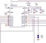
I have a new built as of the attached picture, C1,C2 are 47pF, that I had available C3 1uF and C4 2.2uF.
With U1 and U3 installed as in the picture, U1.p6 remains at 5V and U1.p1 comes up to 3.5V and then drops to 0.9V then jumps to 1.2 and drop agai many times.
After some on-off cycles of the breadboard, now the U1.p1 initiates at 3.8V and remains stable at 4V
With U1 and U3 installed as in the picture, U1.p6 remains at 5V and U1.p1 comes up to 3.5V and then drops to 0.9V then jumps to 1.2 and drop agai many times.
After some on-off cycles of the breadboard, now the U1.p1 initiates at 3.8V and remains stable at 4V
Attachments
Something is definitely not right. U1 pin 1 is pulled low internally through a high value resistor; C3 provides a temporary 5V pulse when first powered up to provide the active high reset signal, after that, it should go low and remain low (<1VDC).
Check that you have 5VDC at U1.p20 and 0VDC at U1.p10; also, all pins are making good contact with the socket and the socket is soldered correctly.
You have 3 processors, correct? Are all 3 doing the same thing?
Also, check the polarity of C3; the positive side should be connected to 5VDC (Vcc) and the negative side to U1.p1.
Last edited:
- Home
- Source & Line
- Analogue Source
- DIY Nixie Tube Display for turntable tachometer