Sorry I didnt wanted to offend you in anyway! I just stated my findings but I am always very open for other opinions and suggestions to try out! I just found a pcb from your SG phono is it available for sale? I would like to try out if possible....") Its not that I am not satisfied with my simple approach I am open for new ideas always! !!!!!!!!
Its not that I am not satisfied with my simple approach I am open for new ideas always! !!!!!!!!
Fellows have a nice day and weekend...
Its not that I am not satisfied with my simple approach I am open for new ideas always! !!!!!!!! Fellows have a nice day and weekend...
I can't say I agree with much of anything you've stated in your post. It's quite easy to determine the relative merits of two devices intended for the same purpose through comparative listening and measurements.
You are of course entitled to your opinion and to even post a dissenting viewpoint.
While I am somewhat swayed by subjective considerations since foolishly I still play [with] vinyl (admittedly the stupidest existing and most irrational format for music reproduction that is still extant) I am a rational designer who believes that measurements while they don't necessarily tell the whole story are useful to help get to the truth.
I do wonder how much of the thread you actually bothered to read before airing your viewpoint here. Had you read it you would have perhaps realized that quite a lot of experimentation, measurement, and even listening went into the design of the pre-amp discussed here.
As a point of reference I have owned several relatively high end LOMC cartridges and still own an Ortofon Windfeld and an Ortofon SPU A95.
I thought the SG had some interesting performance benefits over conventional MC cartridges including better sound stage presentation, low level detail, and imaging, but the tonal balance was very wrong and to me intolerable for more than a few minutes.
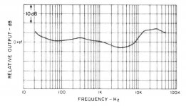
I started with an unequalized pre-amplifier, listened and did some frequency response measurements and basically confirmed the measurements published in hifi magazines decades ago. It also drove me to the logical conclusion that without help this is not a good sounding cartridge in a lot of ways.
My goal was simply to bring the performance up to the level of a decent if not spectacular MC, I think I have succeeded to some extent.
It's unfortunate that it was not developed further and that the cartridge was aimed at the rock bottom of the market; cheap Quad systems and crummy compact stereo systems, and it shows. It has obvious shortcomings as do most transducers.
This is a largely an engineering driven discussion - it's what I do for a living, and it is what my belief system is built around.
I simply wanted to see what I could do with the cartridge, and try to determine what one would sound like if the grossest response aberrations were substantially, bringing the frequency response at least close to what the RIAA standard requires.
As a frame of reference my speaker system is flat to +/- a couple of dB over a range of 200Hz - 20kHz when everything is working correctly. The speaker system is a 3 way diy Onken bass bin on the bottom with JBL horns on mids (2440/2382A) and Fostex T825 on top. Resolution is pretty good, and it's not very forgiving of FR anomalies.
The system is tri-amplified with six channels of power amplification comprising tubes, mosfets and amorphous core transformers. The electronic crossovers (LR4), line stage and phono pre-amplifiers are all of my own design. Sources are TD-124 with ET2/ET2.5 air bearing tonearms and a couple of these strain gauge cartridges. I have digital sources too which are much less trouble, but don't always sound great (but more consistent by far than analog). And it's a work in progress.
My vision of what a good system comprises and sounds like clearly is not yours.
FWIW
I did read a ZYX mc brochure recently and it suggested a microridge for new records, a line contact profile for semi used records and an elliptical for well used records for the best use of tip wear.
They do produce some fantastic sounding LOMC,s and might be something to it
Never heard of this before and it might contain some wisdom and food for consideration...
Regards
David
Last edited:
They're sold out at this point, but I may make some more at some point if there is sufficient interest to justify doing so.
Please use a smaller font!
Ok! Please let me know when available....
Improved EQ
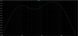
I have felt for a long time that I never got the bass EQ quite right. In addition to that I made a change to the T filter circuit to improve the response in the region between 100Hz and 1kHz.
Four components need to be changed in total.
On the pre-amp card proper change C2 from 0.047uF to 0.022uF - this corrects the cartridge's inherent LF boost below 100Hz.
On the EQ card replace three SMD resistors R1, R4, and R5 with 49.9K 0.1% Panasonic resistors DigiKey PN P49.9KBCCT-ND
The most critical change here is C2 on the pre-amp card as it corrects the LF response which is excessive.
The other changes improve mid-bass through treble region response flatness.
These improvements were driven by other changes in my system as I went to fully active with six amplifier channels, electronic crossovers, and re-equalized the system. The bass response abberation which was tolerable (and very difficult to measure accurately) became intolerable with the new set up because the LF response no longer rolls off quite so early (the wonders of EQ)
See the myriad attachments for details.
REV.06 EQ supersedes all previous versions and the changes are recommended for all completed units as well as any currently under construction.
I apologize for jerking everyone around as I flounder through iteration after iteration of EQ.. LOL I'm still learning how to make these cartridges sing, and it's not an easy task. My measurement hardware,lab space and system have all undergone major upgrades in recent months and I am now starting to get things a bit more sorted out.
The improvement on most systems will be immediately apparent.
Attachments
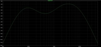
In listening I prefer this EQ slightly to the previous version I published a few days ago, but the differences are very subtle. Only one component value changes between this and the last iteration. R2 on the EQ PCB changes from 33.2K to 30.9K.
The difficulty is that small changes in the EQ affect most of the in band response so even though the amplitude response at any given frequency has only changed slightly the impression can be of a tip in response upwards or downwards or of an accentuation of a specific frequency region.
The behavior of this filter is not intuitive either and that makes it difficult to tune.
Both of the recent filters are a significant improvement in subjective quality over the rev. 5 EQ.
The intent is for the overall presentation to become more spectrally balanced (i.e. neutral) with each iteration. I lack the experience to relate the measurements or even simulations in some cases to the perception of improvement or the reverse, and have to listen to make that determination.
I probably overshare as well in terms of "half-baked" EQs and if some of you feel jerked around by the changes I apologize for that.
Some of you may prefer one or another EQ which is why I suggest trying both of these at least. Systems with a very lean bottom end (not the case here) may be acceptable with REV. 05 EQ as well.
Attachments
Just curious as to how many of you actually built the phono stage; I know of just two so far outside of myself. (26 kits went out the door overall.)
On the subject of stylus retips I am delighted to report that the boron/MR is a marked improvement over a good OEM stylus. (I've got one left)
Make sure if you have a 450 CII or 451C that you use a donor stylus with a red or clear grip that was intended for use on a 450 CII or 451C(R).
The yellow grip with the conical stylus intended for the 460/465 has a slightly larger diameter donut in contact with the transducers, it and the mounting bushing are also made with significantly higher durometer rubber.
Styli with the yellow grip I have concluded do not work well on the 451CR (I have two), but work fine on the 465C. Conversely the OEM red grips also do not work well on the 460/465, their bushing compliance is high enough that at the required tracking force (4gms) they start to collapse. An exception is the "Bliss" which seems to work well on all of these cartridges, but doesn't sound quite as good as the OEM on a 451C.
I am now running a yellow grip equipped boron cantilever MR stylus upgrade on my 465 at 4gms and it sounds quite good. Good channel to channel balance and much better HF extension.
I will be getting one of my OEM red grips re-tipped with a boron cantilever and MR stylus fairly soon.
I believe I may have damaged the jfet CCS chip on the right channel of one of my units, either that or I have a noisy 6CG7. Forgot to plug in the cartridge before powering up on several occasions, either that or I have a bad resistor somewhere - rather low level, and seemingly mitigated for the moment after re-soldering a few a connections and cleaning. (Edit: No not mitigated.. Need to find the issue eventually)
Despite my earnest warnings to never run the pre-amp without a cartridge or load resistors connected to the inputs I failed to heed my warning, and yes I blew one of the LSK389C in the current subtraction circuit a few months ago.
Got some replacements from Trendsetter last week and replaced the bad one. All good now..
Seems like I should have included a protective clamp in the original design, live and learn. It may be possible to add one, but I was concerned about possibly degrading the overall performance of the design and decided not to.
How many of you have actually built one of these? My impression is that I sold a lot of kits and that less than 20% have been built so far.
Apparently the design was something of a hit in Manila and the boards should be available in the Philippines sometime in the future.
Still enjoying the combination Kevin
After about 10 hrs breakin on the boron/mr modification , it simply sounds better than a stock version. Better tracking, quieter tracing , more boyant, much more polished presentation in details. Very fast decays. The rise time are faster than Moving coils and you can hear it
Going back and forth ( one night listening to a stock version and the next night the modified one) for one week alternating every night, what became apparent also is how you could pick one instrument in any song and it would be completely seperate and easy to follow with the mr/boron mod no matter how complex the music got.
The stock version would blend every thing a little more without the same precise instrument outline
Not bad but not in the same league
I plan on doing another total rebuild with a taller machined body and seperating the strain elements so one channel can’t influence the other
Manila ? Who knew !
Regards
David
Last edited:
The ship sailed some time ago, I've no plans in the near term to offer the PCBs again.
The design really would not be too difficult to build point to point which is how I did the very first prototype.
Don't get me wrong I do appreciate the interest! I just don't have the free time at the moment to support another run of the boards.
The design really would not be too difficult to build point to point which is how I did the very first prototype.
Don't get me wrong I do appreciate the interest! I just don't have the free time at the moment to support another run of the boards.
I measured my SG 451C. The angle to glue the cantilever back to the U channel is important. The angle should be 65 degree without VTF compensation. It will be nice to measure the angle under 2-3 grams VTF, too.
Although this thread has gone quiet for three quarters of a year, I can't hep thinking I'm not the only person still watching it.
I'd like to reach back even further, to May of 2018, to revisit one detail. Super, in the discussion of replacement cantilevers you made a nice drawing of the angles involved. But in that drawing the offset of the stylus rake angle is going the wrong direction. I think we all agree that the deviation from 90 degrees in the SRA is to match the cutting stylus. In all modern cutting systems the top of the stylus is closer to the pivot and the tip of the stylus is farther away.
There is not unanimity about how much--some cutters are are set up with one degree offset, some with two degrees. But there is unanimity of which direction it's offset.
If we rotate your drawing so the the rake is two degrees off vertical but in the correct direction, the tracking angle changes too, and winds up at 21 degrees. This is closer to the industry standard than 25 degrees.
This is all academic until we have a measurement of the actual angles with the cartridge in its natural position, meaning with the application of VTF. It would obviously rotate everything in the direction I'm describing, but how much?
Super's original drawing makes this easier to visualize. It's on page 56 of this thread.
- Home
- Source & Line
- Analogue Source
- Playing With Panasonic Strain Gauge Cartridges (And A Dedicated Phono Stage)