David, I'm glad you're still here too--your work on a customized body looked fascinating. I'm going to try something much less ambitious to start, but always interested in seeing what you're up to.
My boards have shipped also. I might see them a day or two before you, Kevin, since I'm on the same coast as OSHPark. It's not a race, of course, I'm just chompin' at the bit to get going.
My boards have shipped also. I might see them a day or two before you, Kevin, since I'm on the same coast as OSHPark. It's not a race, of course, I'm just chompin' at the bit to get going.
Happy to have some fellow voyagers along for the ride. We'll probably spend some time having fun fine tuning the EQ.
Thanx Bodyslam
The new EQ board is too tall for my enclosure and even on the old one had to grind it enough to slide in.
Not a big deal as I have some perf board and the same gold connectors to work it in.
The reason to make a new body would be to increase the mounting height as the stock bodys are to squat in dimension
451,s measure about .580-589” total tip to mounting surface.
For comparisons sake
Spectral MCR reference - .675”
Genesis 2000 sigma - .612”
Accuphase AC-2 -.660”
Most important (speculation at this point) would be to seperate the SG capture material within a new body divider and hope any crosstalk is eliminated
Just need a cattle prod to get going again...
Attachments
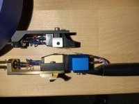

My Versa Dynamics is .400” clearance only and a tight fit and another reason to increase the distance.
Another thought would be to machine a complete body to mount directly to the arm azimuth mounting screw and eliminate any mounting junctions
It would take some faith to go this far 😬
Regards
David
Thanx Bodyslam
Most important (speculation at this point) would be to separate the SG capture material within a new body divider and hope any crosstalk is eliminated
Right...that was another good point you raised. I have enough bodies to try some experiments along those lines. Putting that on the list too.
Not sure how you would maintain the 90° orientation of the transducers if you separate them, this is pretty critical to getting reasonable stereo separation.
I've found as unattractive as it looks that placing some blu tac on the nose of the cartridge substantially reduces the cross talk in the midrange and treble and also eliminates some other weird artifacts due to body resonances. I strongly recommend it, I basically regard them as unlistenable without this "treatment" - unlike a lot of stupid audiophile tweaks this is both cheap and you can verify it with stereo separation measurements, etc.
In other news it looks like my boards will arrive late Monday which is unfortunate as I'd rather hoped to have them today in order to have something to play with over my long week-end. I realized a few days ago that I have taken only two holidays and one vacation day since the beginning of the year. The pandemic has in no sense reduced my work load.. LOL
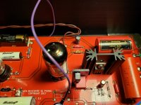
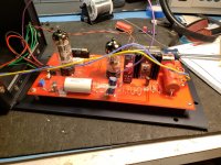
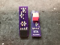
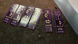
Boards arrived right on time, and I built them up and tested them, I ended up making a minor value change C2 which was previous unpopulated should be 1nF 2.5% WIMA.
I have attached the revised schematic, I have relatively pleased with the performance with the new EQ boards, the additional 1nF provides a better match for the needed boost in the midrange, overall the tonal balance is a lot better. The coldness I have complained about seems to be gone.
I have attached the revised schematic, I have relatively pleased with the performance with the new EQ boards, the additional 1nF provides a better match for the needed boost in the midrange, overall the tonal balance is a lot better. The coldness I have complained about seems to be gone.
Attachments
-
 20200608_172117.jpg374.4 KB · Views: 166
 -
 20200608_170213.jpg437 KB · Views: 178
 -
 20200608_165738.jpg460.6 KB · Views: 238
 -
 20200608_170444.jpg511.2 KB · Views: 227
 -
 20200608_163200.jpg514.4 KB · Views: 243
 -
 20200608_160244.jpg356.3 KB · Views: 248
 -
REV8.1 EQ 2020-06-08.pdf49.6 KB · Views: 168
-
 20200608_214003.jpg421.7 KB · Views: 169
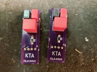
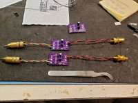
Here is a snapshot of the test jigs I also built up today for setting the input stage bias and for doing response measurements - the network will provide almost exactly 40dB of attenuation when driven by a 50 ohm source and very slightly more when driven by a 600 ohm source.
Attachments
Thanks for the pix Kevin. It looks small and tidy. And it just plugs into the board, right?
The test jigs are for sending a signal from a DAC into your measurement software I take it?
The test jigs are for sending a signal from a DAC into your measurement software I take it?
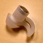
I've been puttering around with building ear mics. Below is a prototype. The simply hook into the ears and sit there looking like ear buds. This one is not yet wired and doesn't have its windscreen.
Electrically they have been dead simple, mechanically not at all. Finding parts that fit and work, figuring out what sizes to use how to cut the tubing, etc. Looks simple and I thought it would be. It's not. 🙂 And I can tell you that silicone rubber is just about as hard to glue as Teflon. I've had to resort to special glues which I am still testing.
Getting there.
I'm hoping to sell these to whoever wants to do low key recordings. Also going to pitch them to the ASMR crowd for the ultimate Ambiosonic headphone experience.
Attachments
The test jigs are for setting the DC bias and for connection to either a signal generator or the generator outputs on my RTX-6001. Either the cartridge or a 700 - 1.21K resistor needs to be connected to the inputs at all times when testing or operating the pre-amplifier, the jfets in the front end can be destroyed if this advice isn't followed. (I have destroyed several unfortunately) If there is eventually another design (there does not seem to be interest here, my offer of gerbers for GB has not garnered any reaction so I will not proceed further down that path) that is one of the problems I will address.
Nice Kevin
I ordered the EQ boards and I was off thinking they wouldnt fit
Somewhere In previous posts you mentioned on J2 a jumper on the pins to reduce overall gain 6 db
And does this apply to the new EQ boards since they configured differently now ?
I would like to reduce gain as an option if possible.
I ordered the EQ boards and I was off thinking they wouldnt fit
Somewhere In previous posts you mentioned on J2 a jumper on the pins to reduce overall gain 6 db
And does this apply to the new EQ boards since they configured differently now ?
I would like to reduce gain as an option if possible.
Have a look at the earlier material posted, you have to remove all of the stuff related to the old EQ and install 2 jumpers as shown. (Just removing some resistors and adding 2 jumpers as shown.) The new EQ is completely incompatible with the earlier design, it also sounds a lot better.
The new network is somewhat lossier than what it replaces so this should help.
The new network is somewhat lossier than what it replaces so this should help.
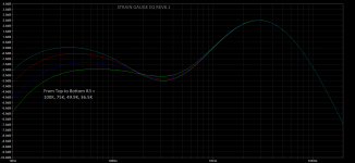
I still feel that the bass response is a bit on the anemic side, never a weakness of strain gauge cartridges so I am at the tweaking game again. Once I have something I like the sound of I will dig out the STRs and run some sweeps to see where I ended up relative to where I've been.
Just tweaking the value of R3, C1 could be adjusted, but I have not seen anything that concerns me at the moment in not doing so.
Changing the value of R3 to 49.9K is definitely a step in the right direction in terms of improving the overall tonal balance.
Just tweaking the value of R3, C1 could be adjusted, but I have not seen anything that concerns me at the moment in not doing so.
Changing the value of R3 to 49.9K is definitely a step in the right direction in terms of improving the overall tonal balance.
Attachments
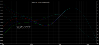
I can, but I am not sure how useful that is without the cartridge phase response.
Here it is. In theory some of the phase shifts might be complementary to the cartridge, but they may not be and I don't have any means of measuring that unfortunately. (I can measure the pre-amplifier, but not the cartridge phase response.)
Here it is. In theory some of the phase shifts might be complementary to the cartridge, but they may not be and I don't have any means of measuring that unfortunately. (I can measure the pre-amplifier, but not the cartridge phase response.)
Attachments
Sorry I deleted the question of a phase plot that you now answered. Excellent
I will order more resistors to play with that bottom end. I could hear what was a rolling train track type of signature which is that boosted low end with my subs.
I have always found when phase is maintained thruout a system , speakers tend to disappear and imaging gets more focused with the best records
The hope of course is that the cartridge and EQ phase shifts are complementary to the original RIAA EQ, however they may not be. LPs don't produce very good square waves although my inverse RIAA and conventional RIAA phono stages do produce a pretty decent square wave even given the bandlimited nature of such systems.
My other playback setup up is a Mutech RM Kanda Hayabusa on a very late Jelco TK-850L on a TD-124 with a 3 phase drive system. Transformers are LL1941 and the phono stage is my latest Muscovite Mini. It's not a very fair comparison but the strain gauge does surprisingly well and is fun to listen to when I am not obsessing about its imperfections that is..
My other playback setup up is a Mutech RM Kanda Hayabusa on a very late Jelco TK-850L on a TD-124 with a 3 phase drive system. Transformers are LL1941 and the phono stage is my latest Muscovite Mini. It's not a very fair comparison but the strain gauge does surprisingly well and is fun to listen to when I am not obsessing about its imperfections that is..
Boards arrived right on time, and I built them up and tested them, I ended up making a minor value change C2 which was previous unpopulated should be 1nF 2.5% WIMA.
Kevin, just let me check. The difference between Rev 8 and Rev 8.1 that you talk about is C2. The other difference on the schematics is the value of R2, decreasing from 41.4K to 41.2K. Is this a significant change also?
Howdy!
R2 is a typo, there is no such value as 41.4K which is why I corrected. C2 = 1nF is a must, large improvement there as original simulations indicated. I am not sure why I left it out.. (forgot?)
R3 is still up in the air, but 49.9K is heading the right way, possibly 56K would be even better..
Some fine tuning is inevitable as the changes are broad in impact even with very small incremental changes.
- Home
- Source & Line
- Analogue Source
- Playing With Panasonic Strain Gauge Cartridges (And A Dedicated Phono Stage)