Gregorjank, most synchronous motors run off 110v even when the turntable is plugged into 240v - there is a resitor/capacitor network to divide the voltage down. Check the label on your motor. If your motor is really 240v the you will need a step up transformer/amplifier as described with Pyamid's SG4. Its probably cheaper to buy a new motor though in the 12v to 110v range.
You wire the motor to the controller. Two ways to switch on: 1. either configure controller to start motor at the application of main power and switch controller on from main turntable switch or 2. Configure a seperate start/45rpm/stop push switch (same as Linn Valhalla etc) - switch is low voltage an can be mounted in a separate enclosure. Mains power direct to controller.
Star Cruiser yes but the 301/401 must be a 110v configuration or you will face same problems as above. A step up transformer/amp will be required. Also max current draw from motor must be <20mA
All, just a progress update. Will have finally finished the instructions this weekend (my new job has been keeping me busier than I expected). A friend in the UK will build one kit as a test to see if there are any changes necessary to the instructions. Then should be ready so New Year is probably about the right timescale for shipping pcbs or kits if all is well.
Last edited:
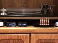
Hi yes the board is finished and working. I had someone build a unit from the instructions and that was successfully completed last week. I will open a thread for a group build at the weekend with the various options and post some final pictures of the system in use on my system.
I have posted a group buy option here:
https://www.diyaudio.com/forums/gro...meter-motor-speed-controller.html#post6086530
https://www.diyaudio.com/forums/gro...meter-motor-speed-controller.html#post6086530
Just finished reading through this thread and I'm stunned once again by the creativity and skill that has gone into pushing this project forward. Thanks to everyone who has shared!
I am planning a speed controller and tach for my upcoming Lenco plinth build, and I'm encouraged to see that others have successfully used this with Lencos. My question is if anyone thinks it would be possible to output the RPM reading to Nixie tubes instead of a LCD display? Wouldn't that look cool?
I don't know how to do it, but if anyone has thoughts, please do share.
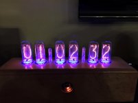
OK, color me bored, but I took a look at doing a Nixie tube tach display. Since this is DIY, I tried to keep the parts count down to a minimum, but there are still a lot of transistors involved (23 N chan FETs and 5 P chan). Good news is it doesn't require any obsolete parts like the 74141, everything is currently available via Digikey.
I did two versions: One uses IN12 tubes the other IN16. The IN16 version is a better looking display and facilitates a vertical display, but is much more difficult to solder the tubes. The IN12 version uses sockets, but the "5" is an upside down 2 and just not as pleasant as the IN16 but better suited for mounting to a front panel.
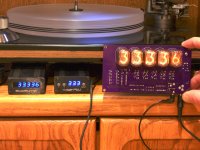
The Nixie display PCB will accept serial data input at 9600 baud from either a RR tach or the Arduino tach via a 3.5mm connection. Since both outputs are not averaged, the Nixie tube display will be "real time" and not subject to the smoothing action of averaging.
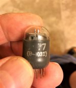
One other thing: It requires an Atmel AT89C2051 pre-programmed with the operating system. I thought about using an Arduino, but they only have one level of interrupt, so I don't know if it would even work and the other problem is I would have to release the source code and a particular mfr has already demonstrated that they are not above pirating a DIY project for commercial use, so I won't be releasing any more source code onto this site.
If there is any interest in this as a group buy or DIY project, I can split this off into a separate thread. Let me know if there is any interest in doing this.
Attachments
Wow. It works and it looks cool!
I’ve suddenly found myself with some time over the past few weeks so I’ve got my Nixie tach project halfway there, using Arduino. I haven’t figured out the code piece yet, or how to solder that tiny surface mount resistor to the RR sensor board, but I can get my IN-12B tubes to light up and be controlled by the Arduino.
I’m still interested in supporting your build because it’s super that you have already made it work, and reliably to boot. Sign me up.
Wow. It works and it looks cool!
I’ve suddenly found myself with some time over the past few weeks so I’ve got my Nixie tach project halfway there, using Arduino. I haven’t figured out the code piece yet, or how to solder that tiny surface mount resistor to the RR sensor board, but I can get my IN-12B tubes to light up and be controlled by the Arduino.
I’m still interested in supporting your build because it’s super that you have already made it work, and reliably to boot. Sign me up.
Would you build the nixie, complete with tubes and all
What would the price be. Shipping to Florida 32725
- Home
- Source & Line
- Analogue Source
- Digital Tachometer for record player (LCD display)