Hi Ducky42,
Wonderful work! I was planning along these lines to house the Arduino and LCD in a small set top box that could sit anywhere near the turntable. The other plan is to incorporate into my planned Nigel Speed controller enclosure. With this in mind, I may implement Pyramid's SG-4 (intending to purchase soon), Nigel's TDA7293 power amp kit (since I already have this) and Arduino tachometer all into one. My issue is there's 2 LED/LCD display. I'm figuring how I can install just one LCD display on the front panel with display showing AC output voltage, SG Set frequency and tachometer reading (either switched selection or all). I've no idea how to merge all these together. Meanwhile, I've already configured the Arduino LCD with I2C with just 4 wires obviously to reduce wiring clutter.
Hi Pyramid, I noticed that you've selected 4 digit LED display for the SG-4 for good reasons. I'm wondering if I could swap to I2C LCD instead. I'm guessing the SG4 firmware have to be altered to suit it. I'm also seriously considering to change the tachometer sensor to your hall sensor module where it seems more suited to under the VPI Classic platter. I don't think I install the IR sensor under the this VPI platter.
Appreciate any comments and feedback.
Last edited:
The SG4 would need hardware and firmware modifications to work with I2C. You will have to use 2 displays.
Dear Pyramid,
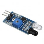
Do you think that the obstacle avoidance sensor for arduino may be used with your code instead of the sensor you kindly recommend?
I am asking this question because I am in Bulgaria and it will be very hard to purchase from the US.
Thanks.
Do you think that the obstacle avoidance sensor for arduino may be used with your code instead of the sensor you kindly recommend?
I am asking this question because I am in Bulgaria and it will be very hard to purchase from the US.
Thanks.
I'm not familiar with the obstacle avoidance sensor. Any sensor that produces an accurate pulse to ground once per revolution will work. By "accurate" I mean that it occurs at the same point in the rotation each time. It should also have fast rise and fall times. People have used optical interrupter circuits, reflective tape with LED emitter/detector pairs or Hall Effect sensors.
Just to let you all know that Pyramid's version of the tachometer is working with the obstacle avoidance sensor for Arduino.
I've been using this sensor which is plainly an IR sensor for Arduino and Pyramid's Hall Sensor, both work nicely as long as the sensor is mounted or adjusted within optimal detection range. No need to alter the code.
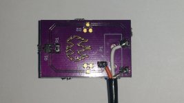
I own a VPI Classic 1. During some tests, I stuck a 5mm disc magnet at 10-15mm from the outer edge of the platter underside, positioned the Hall sensor pcb directly underneath and it read well. Currently, I've not mounted anything permanently till I complete the SG4 speed controller sometime in the future.
I own a VPI Classic 1. During some tests, I stuck a 5mm disc magnet at 10-15mm from the outer edge of the platter underside, positioned the Hall sensor pcb directly underneath and it read well. Currently, I've not mounted anything permanently till I complete the SG4 speed controller sometime in the future.
Attachments
Last edited:
OSH park Magnetic halleffect sensor connection 3.5mm lead
Hi,
Another question to Mr Pyrimid (i think?)
With respect to the Osh park Roadrunner magnitic sensor PCB, I have looked at the digikey website product info for the surface mount socket- respect to a 3.5mm Plug,
ring (+5v) -----to P ? on PCB
TIP (O/P) ----- to P ? on PCB
SCREEN (GROUND) -----to P ? on PCB
I think I allready have it correct haveing buzzed it out with a multimeter -- but could anyone please confirm the above prior to me applying 5 v to the PCB and sending to heaven if i am wrong!!
Thanks, i dont think my nerves will stand another "surface mount session this week?
Me regards
johnny
Last edited:
Thanks to Tauro and Pyramid for their work.
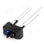
Here is a short video showing my Nigel's Speed Controller with the schematics of Tauro's tachometer and Pyramid software in action.
The sensor used here is the one, showed by coolmaster above.
Thank you guys.
Hi,
I didn't do more experiments to feel which type of sensor is better but both work very well for purpose and intent. With the IR type, you've to make manual adjustment to the on board preset for best usable sensitivity and adjusting for best distance from the platter reflective tape. I used some reflective tape material, not exactly ideal type but it works. As for the Pyramid's hall sensor, I didn't have much choice but slapped a disc magnet under the platter and the sensor board flat under the platter hoping it work and it did work fine. I managed to find individual TCRT5000 photodiode locally and swapped it out at the Arduino IR module (thinking it would perform better) and it worked fine too. I'm guessing there's no performance difference except the TCRT5000 LED is smaller size and look nice. No issues using either type. Due to the VPI Classic design, I intend to use Pyramid's Hall Sensor where I can mount it at the rear left corner. I can't do the same for the IR Sensor. Its a matter of how I want it to look, best hidden away.
Attachments
Last edited:
Thank you lee
Hi cool master, my thanks for the photo, that confirms things nicely.
Best regards as ever 😀 thank you for your time.
Johnny
Hi cool master, my thanks for the photo, that confirms things nicely.
Best regards as ever 😀 thank you for your time.
Johnny
Hi Pyramid and all forum members,
I took the time to read most the posts.
But I still have some questions:
Digital pin 3 of Arduino board connects to the sensor out (figure at post # 171) ?
Digital pin 2 of Arduino board connects to the sensor input on Falcon ?
The Falcon uses a three pole connector, right? What other pins go from the Arduino board to the Falcon and at what position on the p2 plug ?
Do I need any more parts other than the Arduino board itself, the RR hall sensor and the LCD/i2s ?
Can I use any type of Arduino, like the nano ?
Thanks in advance!
Last edited:
Hi Pyramid and all forum members,
I took the time to read most the posts.
-------------snipped-----------------
Can I use any type of Arduino, like the nano ?
Thanks in advance!
The implementation, code and discussion is centered on the Arduino Uno. I used the Uno smd version.
Hi Pyramid and all forum members,
I took the time to read most the posts.
But I still have some questions:
Digital pin 3 of Arduino board connects to the sensor out (figure at post # 171) ?
Yes.
Digital pin 2 of Arduino board connects to the sensor input on Falcon ?
No. Pin 2 is the calibrate output. The constant CALIBRATE should be set equal to the frequency at pin 2 x 120.
The serial output to the Falcon is on digital pin 1 (Tx). For this reason, you should use I2C interface to LCD.
The Falcon uses a three pole connector, right? What other pins go from the Arduino board to the Falcon and at what position on the p2 plug ?
The Falcon uses 3.5mm stereo audio connector, TIP/RING/SHIELD (TRS). The level into the Falcon is RS232 on shield (gnd) and ring (Rxd). You will need to add the RS232 shield PCB to convert the TTL output from the Arduino to RS232 for the Falcon (see posts 51 +)
Do I need any more parts other than the Arduino board itself, the RR hall sensor and the LCD/I2C ?
See Above.
Can I use any type of Arduino, like the nano ?
Thanks in advance!
Most of the work was done on the Arduino Uno R3. If you use a different variant, the pins for SCL & SDA (I2C to LCD) may be a different location on the output connectors, but it should work if you get the wires to the correct locations.
Thank you Pyramid and Coolmaster!
Will order the RS232 shield and the LCD, I have more than one Arduino here, hope I can adapt to use the nano to fit inside a case about the same size as the Falcon.
Regards
Will order the RS232 shield and the LCD, I have more than one Arduino here, hope I can adapt to use the nano to fit inside a case about the same size as the Falcon.
Regards
I noticed the Arduino RS232 shield is rather expensive.
Would there be any interest in a DIY version?
Surface Mount or Thru-hole?
If it were done SMT, there would be no mounting holes and it could be mounted with double sided tape. One 16 pin SOIC, 4 caps.
Would there be any interest in a DIY version?
Surface Mount or Thru-hole?
If it were done SMT, there would be no mounting holes and it could be mounted with double sided tape. One 16 pin SOIC, 4 caps.
I noticed the Arduino RS232 shield is rather expensive.
Would there be any interest in a DIY version?
Surface Mount or Thru-hole?
If it were done SMT, there would be no mounting holes and it could be mounted with double sided tape. One 16 pin SOIC, 4 caps.
I can find one for less than 1 dollar here in Brazil, and there is also many on eBay: 2Pcs RS232 To TTL MAX3232 Converter Adaptor Module Serial Port Board Arduino | eBay
Did I find the wrong board ?
Ah...very good. Exactly what I had in mind to construct.
I did an e-Bay search for 'Arduino RS232 shield' and the parts that came up were $25, but had connectors that would plug into the Uno.
If anyone is interested in building their own: OSH Park ~ RS232.ZIP
I did an e-Bay search for 'Arduino RS232 shield' and the parts that came up were $25, but had connectors that would plug into the Uno.
If anyone is interested in building their own: OSH Park ~ RS232.ZIP
- Home
- Source & Line
- Analogue Source
- Digital Tachometer for record player (LCD display)