Great!
My problem here now is to find a seller that has all the parts, to keep shipping costs low...
My problem here now is to find a seller that has all the parts, to keep shipping costs low...
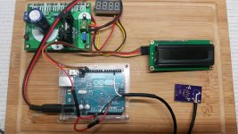
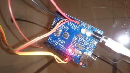
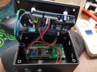
This is how I rigged up the Arduino/LCD with serial interface piggybacked to LCD/Phoenix Hall Sensor on a test bed. Its powered from a used old modem wall wart through a general purpose LM317 adjustable regulator.
I prefer the I2C Serial interface as it cut down on the number of wires needed to interface to LCD module. I bought a high quality LCD module and found it a little differently configured, I had to mod the I2C module to adapt to this particular LCD type referring to LCD product data sheet. If I had slapped it on without the mod, the LCD module would have fried in 10 seconds.
I prefer the I2C Serial interface as it cut down on the number of wires needed to interface to LCD module. I bought a high quality LCD module and found it a little differently configured, I had to mod the I2C module to adapt to this particular LCD type referring to LCD product data sheet. If I had slapped it on without the mod, the LCD module would have fried in 10 seconds.
Attachments
Last edited:
Thanks!
I found a Nextion 3.5 inches left from a PID project of a "hi-end" espresso machine.
This uses i2c native , it has many more functions like graphic interface and touch screen , but I´m considering to adapt the code to use it and check the update speed of the display.
That four digit display you use as a volt meter?
To keep everything small , I also considered the use of a simple 5 or 6 digits display like the one in your picture, just for the rpm. But I can´t find any with i2c...
Thanks!
That four digit display you use as a volt meter?
To keep everything small , I also considered the use of a simple 5 or 6 digits display like the one in your picture, just for the rpm. But I can´t find any with i2c...
That little 4digit LED is to monitor the general purpose DC regulator preset voltage powering the Arduino in this case. Its an integrated LED DC voltmeter pulled from some inferior DC regulator kit.
Hello,
I'm trying to build this tachometer but I'm getting wrong readings.
I've build the sensor using a A3144 hall sensor, a 10K resistor and a 104 capacitor, just like the picture attached.
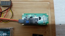
I'm using a 16x2 LCD with a I2C module, connected to SCL, SDA, 5V and GND on the uno board.
The sensor is connected to digital pin 3 (signal), 5V and GND from the uno power section.
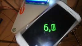
I'm using a low RPM motor (from a record cleaner machine, because my VPI motor isn't operational right now). Using a stopwatch and the RPM calculator app I get around 6 RPM (from both methods) as you can see on the picture attached.
The arduino tach displays an average RPM of 35.7
This is the code I'm using:
The arduino UNO board I'm using is a clone (UNO R3 MEGA328P CH340G), with 2 cristals: one rated 12.000 near the USB port and one rated HY16.000 near Mega328P chip.
I tried to find how to get the frequency at pin 2 but I could not find anything online (this is my first time with arduino and programmig).
What can I do to fix this? Thanks!
I'm trying to build this tachometer but I'm getting wrong readings.
I've build the sensor using a A3144 hall sensor, a 10K resistor and a 104 capacitor, just like the picture attached.
I'm using a 16x2 LCD with a I2C module, connected to SCL, SDA, 5V and GND on the uno board.
The sensor is connected to digital pin 3 (signal), 5V and GND from the uno power section.
I'm using a low RPM motor (from a record cleaner machine, because my VPI motor isn't operational right now). Using a stopwatch and the RPM calculator app I get around 6 RPM (from both methods) as you can see on the picture attached.
The arduino tach displays an average RPM of 35.7
This is the code I'm using:
Code:
// Uses I2C LCD interface.  SDA and SCL left most pins on 18pin header next to AREF
// Check I2C address using Scanner example file; address range 0x20-0x27 and 0x38-0x3f.
// RPM is computed using counter developed in Timer2 interupt @ 32µSec rate.
// Timer0 is disabled so delay(), millis() and micros() will no longer function (hangs the UNO).
// RPM calculation is: CALIBRATE/counter.  CALIBRATE = freq at digital pin 2 (PB2) x 120
// At timer2 = 32.000 µSec, PB2 should be 15,625 Hz and CALIBRATE should be 1,875,000.
// If USE_AVERAGE = true, display data will be averaged MAX_AVG times. Pratical MAX_AVG values: 2-8
// Set USE_AVERAGE to false to disable averaging.
// DO NOT average the data going to the PSU on serial port.
// Code written by Pyramid (Bill), modified by Packgrog, modified by Altanir

#include <Wire.h>
#include <LiquidCrystal_PCF8574.h>


LiquidCrystal_PCF8574 lcd(0x27);

const int SENSOR_PIN = 3;             // input on PB3
const float CALIBRATE = 1873440;      // equals freq @ PB2 x 120
const byte MAX_AVG = 8;               // set # of averages
const boolean USE_AVERAGE = false;     // set to false to disable averaging


unsigned int counter, rpm_count = 0;
unsigned long msec = 0, last_update_time = 0;
byte ms_prescale = 0, avg_idx = 0, avg_count = 0;
float rpm, rpm_avg_buffer[MAX_AVG];
boolean is_update = false, is_done = true, is_stopped = true;


// the setup function runs once when you press reset or power the board
void setup()
{
  Serial.begin(9600);
  pinMode(LED_BUILTIN, OUTPUT);
  pinMode(2, OUTPUT);                    // Calibrate output
  pinMode(SENSOR_PIN, INPUT_PULLUP);     // PB3 trigger input

  TCCR2A = 0x02;    // CTC mode
  TCCR2B = 0x04;    // ÷64 Prescalar
  TCNT2 = 0;
  OCR2A = 7;        // 32µSec rate
  TIMSK2 = 2;       // enable OCR2A interrupts
  TIMSK0 = 0;       // disable timer0 interrupts

  lcd.begin(16, 2);
  // lcd.createChar(0, DISC_ICON);
  lcd.home();
  lcd.clear();
  lcd.setCursor(3, 0);
  lcd.print("Tachometer");
  lcd.setCursor(0, 1);
  lcd.print("  RPM: --.---");
  lcd.setBacklight(125);
}

// the loop function runs over and over again forever
void loop()
{
  if (is_update && is_done) {
    rpm = CALIBRATE/rpm_count;      // compute RPM

    if (rpm > 28 && rpm < 100) {
      Serial.print(rpm, 3);         // Don't average the serial data!
      Serial.print('\n');
      Serial.print('\r');

      if (USE_AVERAGE) {                        // check if we are averaging
      rpm_avg_buffer[avg_idx++] = rpm;        // save current value in circular queue and move pointer
      if (avg_idx == MAX_AVG) avg_idx = 0;    // check for overflow (yes, reset pointer to beginning of queue)

      if (avg_count == 16) {                  // Don't display average for at least 16 readings
      float rpm_total = 0;
      for (int x = 0; x < MAX_AVG; x++) {   // Recompute RPM as average of last MAX_AVG readings
      rpm_total += rpm_avg_buffer[x];
      }
      rpm = rpm_total/MAX_AVG;
      digitalWrite(LED_BUILTIN, HIGH);
      }
      else {
     avg_count++;            // leave RPM as is, increment count
      }
      }
      lcd.setCursor(7, 1);
     lcd.print("           ");
      lcd.setCursor(7, 1);
      lcd.print(rpm, 3);
    }
    is_done = false;              // reset trigger flag
    is_stopped = false;           // platter turning, reset flag
    last_update_time = msec;      // Start Activity timer
    mydelay(250);                 // for at least 250mSec
  }

  if (!is_done && digitalRead(SENSOR_PIN) == HIGH) {  // check for no trigger input
    is_update = false;                                // reset for interrupt routine
    is_done = true;
    mydelay(50);
  }

  if (!is_stopped && (msec - last_update_time > 2500)) {  // check if platter stopped
    is_stopped = true;                                    // yes, flag it
    lcd.setCursor(7, 1);                                  // blank reading
    lcd.print("--.---");
    avg_count = 0;                                        // reset average count
    digitalWrite(LED_BUILTIN, LOW);
  }
}

void mydelay(int time_loops)  // range 1mSec to 65.535 Sec.
{
  for (int x = 0; x < time_loops; x++) {
    delayMicroseconds(300);
  }
}

ISR(TIMER2_COMPA_vect)  // timer 2 interrupt: 32µS rate 8 bit auto reload
{
  counter++;
  digitalWrite(2, !digitalRead(2));     // Toggle TP PB2

  if (digitalRead(SENSOR_PIN) == LOW && !is_update) {
    rpm_count = counter;                // capture value
    counter = 0;                        // reset counter
    is_update = true;                   // flag for main routine
  }

  if (++ms_prescale == 31) {            // check for msec update
    ms_prescale = 0;                    // reset counter
    msec++;                             // increment msec count
  }
}
The arduino UNO board I'm using is a clone (UNO R3 MEGA328P CH340G), with 2 cristals: one rated 12.000 near the USB port and one rated HY16.000 near Mega328P chip.
I tried to find how to get the frequency at pin 2 but I could not find anything online (this is my first time with arduino and programmig).
What can I do to fix this? Thanks!
Attachments

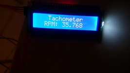
You need a faster motor. The timer ISR is incrementing a 16 bit counter 31250 times per second. It assumes the platter is turning between 28 and 100 RPM. If it is turning 6 RPM, that is 10 seconds per rev. In that time, the 16 bit counter will overflow and wrap around several times giving a false reading. If you are reading 35.7 RPM, it is taking 10.068928 seconds to make one rev (5.9589 RPM). The 16 bit counter is overflowing 4 times plus a count of 52521 which creates a reading of 35.7 RPM. This could probably be trapped to prevent this from happening, but just use a motor that produces a reading in under 2.5 seconds and the display will read correctly.
Thanks Bill! For a moment I thought something were wrong with the arduino I bought!
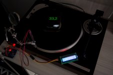
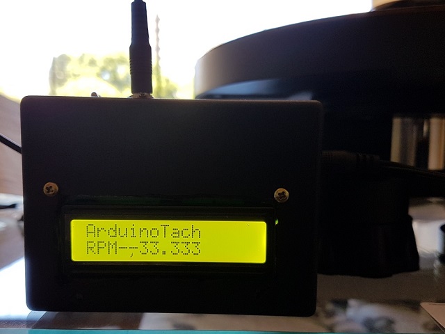
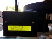
I took my previous turntable from where I had it storaged and tested! I'm now getting right measurements! At 33.3 rpm the tachometer displays 33.299 and for 45 rpm it displays 45.1.
This turntable does not have pitch control, so I fine tune its speed by passing electrical tape around the subplatter... I'll see what I can do to get a little more precise!
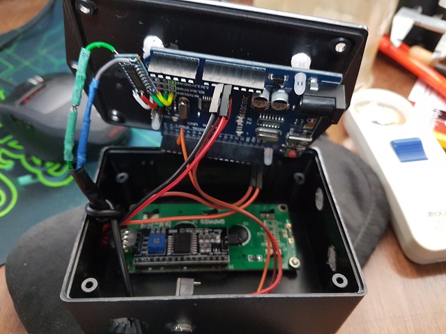
Now all I need is a nice case and some tweeks like a on/off switch.
I'm also building a SG4 controller to use with the VPI and it will be a lot easier to get more accurate speeds.
Thanks a lot!
I took my previous turntable from where I had it storaged and tested! I'm now getting right measurements! At 33.3 rpm the tachometer displays 33.299 and for 45 rpm it displays 45.1.
This turntable does not have pitch control, so I fine tune its speed by passing electrical tape around the subplatter... I'll see what I can do to get a little more precise!
Now all I need is a nice case and some tweeks like a on/off switch.
I'm also building a SG4 controller to use with the VPI and it will be a lot easier to get more accurate speeds.
Thanks a lot!
Attachments
BTW, the RS232 Shield that I used was not that expensive. Only $15. Amazon.com: RS232/RS485 Shield for Arduino: Computers & Accessories
The adapter that I used was only another $5.50 shipped, which i wired up with half of a RadioShack 3.5mm cable. Amazon.com: DB9 Male Signals Breakout Board RX TX GND 3-Pin: Home Audio & Theater
While there are DB9-to-3.5mm TRS cables, the Falcon has two of the connectors swapped from the standard.
My unit still works like a charm, and I haven't wanted to mess with it since I got it running. I have other sound quality-related setup gripes now. 😛
This guy makes some slick looking cases: 20x4, 16x2 LCD case for Raspberry Pi 2/3 model B / Pi 1 Model B+ Zero, Ardunio | eBayNow all I need is a nice case and some tweeks like a on/off switch.
I had a remote-control power switch meant for outdoor lights that I ended up using, but that'd be a little expensive for simple use. This looked convenient, though: Amazon.com: 5.5mm x 2.1mm Inline Power Switch For Arduino Boards and LED Light Strips by Corpco: Home Audio & Theater
If you can't track down a Falcon or Eagle (they're nearly impossible to find now), and aren't inclined to try assembling your own motor, you might consider looking at the Jasmine DC motor pods. Can't be auto-controlled like a synchronous AC motor, but the tach can still help you dial in the speed with the knob on top of this (fair disclosure, I have never tried this item): Jasmine TM-R501 Turntable Motor | eBay
Thanks for the suggestions, Packgrog.
I already bought a case, it will be a simple black project case made of aluminium. For the switch, I'll use a toggle SPST!
I already bought a case, it will be a simple black project case made of aluminium. For the switch, I'll use a toggle SPST!
You could also use the RR sensor with Hall Effect IC.
Q1 is the AH337 sensor IC SOT23 package. Digikey PN: AH337-WGCT-ND
D1 & D2 are 5V zeners SOT23 package Digikey PN: BZX84C5V1-FDICT-ND
R1 is a 1.0K 0805 resistor Digikey PN: P1.0KJCT-ND
P1 is a 3.5mm RA socket Digikey PN: CP-3523SJCT-ND
Bill,
I appreciate you sharing the RR sensor board design. I ordered a few boards from Oshpark and built up the boards today. I did find that there's a slight error in the BOM. As you point out, the board is designed for an R1 SMD resistor size 0805. The referenced part # is a 0402 SMD part, which is too small for the pads on the board. I ordered the resistors listed above but fortunately had some 1K 0805 resistors in my parts box so it wasn't a big problem.
Thanks,
---Gary
Sorry, my mistake. BOM corrected on OshPark website (should be P1.0KADCT-ND).
FYI, the value isn't critical; any value from 560-22K will work.
Hello Bill,
I finished the tachometer, just need to find a good case for it now.
But I noticed something on the sketch, at the lines that send the data to the serial output, the compiler showed an error that was easy to correct to this:
"Serial.print('\n');"
"Serial.print('\r');"
But, if both commands are sent, as expected, the serial output shows like:
"...
33.333
33.333
33.333
..."
But if I leave just the first command "[Serial.print('\n');]", then it´s like:
"...
33.333
33.333
33.333
..."
I guess the correct output for the Falcon is this last one, or do we need to have a blank line before each new measure?
PS: Now I noticed it´s a problem with the forum text editor... it "eats" some characters at the end of some lines!?!
Last edited:
zmck- Blank lines shouldn't hurt, the Falcon will ignore them, but it's probably best to eliminate them.
Yeah, you have to be careful about copying the text from one of the scrolling "windows"; I've noticed the html function for this randomly drops characters. Better to copy the script from one of the .txt files, that way it is complete.
Yeah, you have to be careful about copying the text from one of the scrolling "windows"; I've noticed the html function for this randomly drops characters. Better to copy the script from one of the .txt files, that way it is complete.
Hi,
I have managed to get the "hello world"' sketch working so I assume that I have the correct pins for the I2C LCD. I have used A4-SDA and A5-SDL. Hall effect sensor connected to PWM -3. I then took Pyramids sketch and substituted:
#include <LiquidCrystal_PCF8574.h>
LiquidCrystal_PCF8574 lcd(0x3f);
For
#include <LiquidCrystal_I2C.h>
LiquidCrystal_I2C lcd(0x27,16,2);
I managed to upload but nothing happens. All I get is the upper line lights up.
What have I done wrong? Its difficult to make out any of the connections on the youtube videos.
Thanks,
kffern
If you get dark rectangles for the top line and nothing for the 2nd line, the LCD is not getting initialized.
You may be mixing function calls between the two I2C libraries. If your LCD display uses an interface PCB with a PCF8574 chip, I would not make changes to my sketch and use the wiring diagram that I used.
What version Uno are you using (SDA and SCL are located on different pins for different versions of Arduino)?
You can try this sketch to search for I2C devices; it checks all 128 addresses and reports which ones respond: https://playground.arduino.cc/Main/I2cScanner
Also, please show your code from the beginning up to the start of loop() for both your "hello world" code and the modified tach code.
Hello,
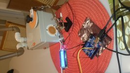
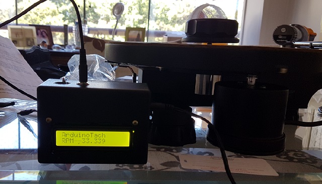
At last I managed to attach the completed prototype to my AVID Ingenium.
The results were suprising, I had no idea about how sensible is the adjustment of the belt tension, any "micro" adjust has a great influence in the measured rpm.
My Falcon PSU is still in transit from US, I hope the rpm data function from the TTL>RS232 board will work. One odd thing I confirmed about these Arduino boards is that unlike our audio equipment, where the output (usually marked as OUT) of a source must be connected to the input of the other equipment, with the Arduino boards (at least the one I tested) the TX signal must be connected to the TX of the destination board, not TX->RX. I don´t know how will this TTL>RS232 board work, must test with the Falcon when it arrive here.
I ordered a PRO MINI to miniaturize the project to match the Falcon size, when I tried to program it with a USB->TTL board, I realized that the only way is to connect TX->TX and RX->RX... strange...
Thanks to Bill and all other forum members for all the help with this project.
I consider it an essential device for anyone with a turntable that allows fine adjustments to the RPM, usually the strobo lights use the frequency of the AC line as a reference and this tachometer actually measure the rpm independent of the AC line frequency.
Here are some pictures:
Attachments

Last edited:
Hi Bill,
I did run the scanner sketch and got "'I2C device found at address 0x27 !
The board is actually a IDUINO UNO - pdf attached. It says A4 is SDA and A5 is SCL but also has SDA and SCL pins that are near to the AREF pin.
I will have another try when I get back from work today.
Which pin do you use for the hall effect sensor?/
Thanks for your help.
kffern
Attachments
Success I think! I removed the 16,2 at the end of this - LiquidCrystal_PCF8574 lcd(0x27);.
No response from the sensor when I move a magnet across the hall effect sensor.
Arduino Hall Effect Magnetic Sensor ARD2-2203 | eBay
Will have a look tonight as I;m late for work.
Regards,
kfferrn
No response from the sensor when I move a magnet across the hall effect sensor.
Arduino Hall Effect Magnetic Sensor ARD2-2203 | eBay
Will have a look tonight as I;m late for work.
Regards,
kfferrn
Are you aware that the sensor detects only one of the magnet poles?
Also, there are different kids of sensors, mine looks just like your picture but is labeled A3144.
It must be a unipolar (non latching) sensor, that sends a signal to the digital input of the Arduino every time it senses a south magnetic pole, and stops sending the signal when the magnet is removed.
The latching kind of sensor is different, it sends the signal when it senses a south magnetic pole, but only stops sending the signal when it senses a north magnetic pole.
Your sensor has other number, so it must not be unipolar, better check it´s specs.
Last edited:
- Home
- Source & Line
- Analogue Source
- Digital Tachometer for record player (LCD display)