There's a lot more assignment going on in your interrupt handler. Is this less of an issue for delays due to the use of the higher priority timer and lower level interrupt handling?
Unfortunately, there is only one level of interrupt priority with the '328, so there doesn't seem to be a way to do accurate low level timing if more than one interrupt is active; a severe limitation and one that makes things much more difficult. It's why I had to disable the Timer0 interrupt used by the Uno OS for its delays. I have to get everything done in under 32µSec, which would be easier if done in assembly language; it works, but from the operation of delayMicroseconds(), it must be taking ~22µSec (or 352 assembly instructions; in the RR tach, I use less than 10). As a result, the main code is running at 1/3 of its normal speed, so 5.33 MIPS instead of 16.
Are you actually using digital pin 2? I'm a little lost on the "pinMode(2,OUTPUT);" line. I currently have that pin attached to my LCD with the crazy wiring, but could easily shift it up. Of course this may be moot once my own I2C LCD shows up.
I use digital pin 2 to calibrate the timer routine. The constant CALIBRATE (used to compute the RPM value) should be the frequency at pin 2 x 120. It could be disabled and the code commented out, but it is a handy way to see if the timer ISR is working properly and to calibrate the reading. Pin 2 is toggled by the timer 2 ISR everytime it is called. It could easily be moved to any other pin by redefining it. I use pin 3 as the trigger input, but the trigger itself is not generating an interrupt, so it too could be moved anywhere.
Funny how all of the threads I encountered about float values not printing properly with "Serial.print(RPM);" never once mentioned using the second parameter as in "Serial.print(RPM,3);".
I find the on-line resources spotty and contradictory at best. I spent hours on trying to get simple tasks done for lack of accurate documentation.
Last edited:
Still not sure I fully understand (getting lower level than I'm likely to grasp quickly), but that's fine. D0 and D1 for Serial, D2 reserved, and D3 for sensor input, with all other digital pins free for use. Check.I use digital pin 2 to calibrate the timer routine. The constant CALIBRATE (used to compute the RPM value) should be the frequency at pin 2 x 120. It could be disabled and the code commented out, but it is a handy way to see if the timer ISR is working properly and to calibrate the reading. Pin 2 is toggled by the timer 2 ISR everytime it is called. It could easily be moved to any other pin by redefining it. I use pin 3 as the trigger input, but the trigger itself is not generating an interrupt, so it too could be moved anywhere.
So you have the green and white wires of your LCD going to the unlabeled pins on the Uno board? Not sure how you figured out how to set that up, but kudos.
What's with the white wire soldered to that chip? Just extra grounding?
Thanks for the updates/feedback! Good stuff!
Hi,
Maybe this what we maybe looking for. I found this Texas Instrument micro MSP432P401R LaunchPad that can be program using the Energia software that it is same as the Arduino IDE. You can program it using the same software sketch as the Arduino with not problem It's run at 48mhz and just cost only 13 dollar in Mouser. Just for your evaluation / consideration.
Attached it is the link for the datasheet download.
link:MSP-EXP432P401R SimpleLink? MSP432P401R LaunchPad? Development Kit | TI.com
Still not sure I fully understand (getting lower level than I'm likely to grasp quickly), but that's fine. D0 and D1 for Serial, D2 reserved, and D3 for sensor input, with all other digital pins free for use. Check.
Contact me at billatphoenix-engrdotcom if you want me to explain it further. Not sure what you don't understand, so expand on that if you contact me.
So you have the green and white wires of your LCD going to the unlabeled pins on the Uno board? Not sure how you figured out how to set that up, but kudos.
The pins are labeled on the bottom of the Uno PCB. When you get your LCD, power it up and turn the contrast pot on the I2C interface PCB until the display shows a row of solid blocks on the top line and blank display on the bottom. Until the contrast is set correctly, you have no idea if the display works or not.
What's with the white wire soldered to that chip? Just extra grounding?
That's 5V output to the Hall Sensor PCB. Shield is ground, Red is trigger out.
Maybe this what we maybe looking for. I found this Texas Instrument micro MSP432P401R LaunchPad that can be program using the Energia software that it is same as the Arduino IDE.
I think it's a bit of overkill; 32 bit ARM processor with DSP core? Could be just a tad complicated to program.
All we're trying to do is capture a (accurate) time base count and take the inverse x 60 to compute RPM on a LCD display. This could easily be done on a low pin count 8051 clone i.e. AT89C2051, although I don't think that chip supports C and it isn't ISP.
For those who prefer the old analog method of reading the speed, here's a $13 version of the $100 KAB strobe light: [url]https://www.tindie.com/products/bot_thoughts/turntable-strobe/[/URL]
Print a free on-line strobe disk, and you're making hay for <$15.
Hi all,
A big thank you to Pyramid for sharing his code. I tried it earlier, just altering to suit my I2C LCD display. Am still using the IR sensor at Pin 3.
Much earlier today, At long last, I've achieved interfacing my Midas LCD display to the common I2C adapter and making it work. Just plugging the 16 pins to the LCD will not work. I had to experiment and figure it all out with a breadboard and careful hooking up.
After establishing the connections are all correct and with display, I proceeded to reverse engineer the common I2C adapter to suit this particular display. What I did was desolder, remove the contrast pot at the adapter, disconnect the pot ground pin from the adapter ground, link a wire from pot to Pin 15 which is assigned as "Vee" on this LCD and not "Anode/LED+" as found on other 1602 lcd. Lastly, the backlight jumper at the I2C is not used. At last my Midas LCD works hereon and with minimum wires to the Arduino.
I gave Pyramid's sketch a try, and oh yeah, vastly superior. I'm not sure that I could have improved my own version any further, but Pyramid dug deeper and came up with a far better solution. Cheers, man!
Tweaks that I made for my upload were as follows:
I checked the speed with Turntabulator again, and with Pyramid's updates, the app was showing 33.33 to 33.35 (I was getting 33.30 with my best version of the software). Pretty much perfect, lining up with what I would get from a Technics deck, and falls into the margin of error for the Turntabulator app! Excellent!
Thanks very much, folks! This has been a fascinating learning experience and solves a big gripe that I've been having with nearly every turntable that I've owned (except the Technics, which just never sounded as good as even a modest belt drive). Cheers, folks!
Tweaks that I made for my upload were as follows:
- Changed LCD config, after shifting the wires up to keep port 2 clear,
- Refactored for readability (it helps me to more easily understand what's going on, but no real functionality was changed),
- Commented out the averaging (very slick solution, but not useful for me, as I find it more helpful to see when the individual fluctuations are more dramatic, to tip me off to a different system problem),
- Commented out the custom character that signifies a pulse being handled (the LCD refresh rate is TERRIBLE, so it wouldn't finish drawing the blip before trying to blank it out again),
- Commented out blanking of the whole line after "RPM: " (again, TERRIBLE refresh rate on the LCD, so this caused an annoying flicker on the numbers).
I checked the speed with Turntabulator again, and with Pyramid's updates, the app was showing 33.33 to 33.35 (I was getting 33.30 with my best version of the software). Pretty much perfect, lining up with what I would get from a Technics deck, and falls into the margin of error for the Turntabulator app! Excellent!
Thanks very much, folks! This has been a fascinating learning experience and solves a big gripe that I've been having with nearly every turntable that I've owned (except the Technics, which just never sounded as good as even a modest belt drive). Cheers, folks!
Attachments
Hmm....I wonder why your LCD was slower to update? I used a positive display, was yours negative (light characters on a dark background)?
Also, you don't need to comment out all of the averaging code. Just set constant AVERAGE to false, recompile and it won't average and there will be no change in performance.
If you have an accurate frequency counter, look at the frequency at pin 2. It should be 15,625 Hz, but can vary slightly. To calibrate the tach, set the constant CALIBRATE equal to the pin 2 freq x 120.
Yep. https://youtu.be/Mkioe1PUOSkHmm....I wonder why your LCD was slower to update? I used a positive display, was yours negative (light characters on a dark background)?
Note also that I have LEDs flashing both when the IR sensor triggers a pulse as well as when the serial shield sends a message to the Falcon. The delay between these two is barely visible, but both pulses are quicker than the LCD could ever hope to refresh.
Oh, I understood that. Switching the constant would absolutely be a better choice for someone who is less comfortable tinkering with C code.Also, you don't need to comment out all of the averaging code. Just set constant AVERAGE to false, recompile and it won't average and there will be no change in performance.
In my case, I just found that commenting out the blocks of unused code and related variables made it easier for me to focus my attention on the important parts of the code. It's also immensely satisfying (if completely unimportant in this case) to see the memory usage of the compiled code drop down. 😛
Sadly, I do not. My wiring tool kit is a nice enough starter kit, with a modest voltmeter, but nowhere near what you're likely to have on hand.If you have an accurate frequency counter, look at the frequency at pin 2. It should be 15,625 Hz, but can vary slightly. To calibrate the tach, set the constant CALIBRATE equal to the pin 2 freq x 120.
Last edited:
Yep. https://youtu.be/Mkioe1PUOSk
Note also that I have LEDs flashing both when the IR sensor triggers a pulse as well as when the serial shield sends a message to the Falcon. The delay between these two is barely visible, but both pulses are quicker than the LCD could ever hope to refresh.
That may account for the difference. On the positive display, the flashing icon was not objectionable and the refresh of the RPM reading wasn't visible with the naked eye. On the downside, a back-lit positive display is BRIGHT! There appears to be a function in the I2C library to adjust the backlight brightness from 0-255, but it does not function on my display; it's either on or off. If someone wants to try this, look for an LCD display that dims.
There is a delay of 250mS after the icon is displayed; the magnet pulse only lasts ~8mS @ 33 RPM (shorter at 45) so I had to extend the time so it was visible on my display. You could try increasing this to 500 or 750mSec to smooth this out. I wouldn't go any longer than 750mSec or the icon will be on longer than it is off during 45 RPM mode.
I originally used the built-in LED for the sensor indicator, but I thought if someone puts this in an enclosure, they won't see it. I'm now using the built-in LED to indicate when averaging starts/resets, but it's more of a debug thing so that I knew it was working right.😎
tauro0221 & pyramid-
Thanks so much for sharing this project with the DIY community. I plan on building this to go with my SG-4 power supply. I have a small aluminum enclosure left over from another project that I plan to use to house this project. I'll post pictures when I get all the parts together.
Thanks so much for sharing this project with the DIY community. I plan on building this to go with my SG-4 power supply. I have a small aluminum enclosure left over from another project that I plan to use to house this project. I'll post pictures when I get all the parts together.
@Ducky42 I know some other people who are envious of your PSU implementation (I still love it as well, even if I no longer need it), but who don't have you skill to build one. I'd be very interested in seeing what you come up with for the tach!
Hi all,
I've built 2 units of Nigel Speed Controller for friends with success and slapped on an affordable Made in China LCD voltmeter panel. These meters are cheap and trust me they don't last very long, where the first consequence of it dying is the LCD start to get dimmer and dimmer. Replacement of the meter is the only resort. There's nothing to repair inside, been there done that.
After finishing the 2nd build, I'm about to build a 3rd one for myself but with more sophisticated features inside.
What interest and appeal very much to me is Pyramid's SG4 signal generator and this Arduino Uno project that I could implement in the 3rd build and better than than the earlier builds.
If I want frequency, then I've to slap on another meter. I don't want to have too many displays on the front panel. There's only so much space at my enclosure for just 1 display.
What I desire very much is to mount a 16 X 2 LCD (either ones I already have, Red & Blue) that would or could display output voltage, set frequency and detected platter speed (Arduino?). Maybe I'm thinking too plainly, is there some way to have all these displayed on one LCD on the front panel?
Last edited:
That's a pretty cool idea, coolmaster: Tach and motor controller in same case sharing same display, even if not including auto-speed-adjustment. I'd be surprised if that weren't entirely possible. I suspect you'd be sending data from the SG4 to the Arduino, leaving the Arduino to handle all the display aspects and presumably also the user interface functions. That would be very cool to see!
That does remind me of someone else's project that seems to be functional but never did become fully available: the MagicQuartz. MagicQuartz, the Computing True Sine Turntable Speedbox | MATE-LABS Very similar to Pyramid's tach and PSU products (ie: includes auto speed adjustment), but built into a single, less pretty but highly configurable package. I guess the guy is too busy with school to finalize his kit. I have *NO* idea how the power output quality might compare to Pyramid's designs.
Maybe some day I'll find the time and money to go take some trade school electrical work classes so that I can have some confidence to tackle one of the PSU builds. :/
Bill, will your hall sensor work with this tach?
If so, is there any info on components to populate the board.
Thanks, Greg
If so, is there any info on components to populate the board.
Thanks, Greg
Bill, will your hall sensor work with this tach?
If so, is there any info on components to populate the board.
Thanks, Greg
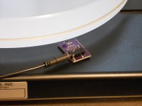
Yes it will. You have to supply 5VDC to the sensor on the "Ring" connection (3.5MM TRS). The output pulse is on the Tip. Sleeve is ground.
I've posted the link to the OshPark site for this several places. The BOM is on the OshPark site.
@Ducky42 I know some other people who are envious of your PSU implementation (I still love it as well, even if I no longer need it), but who don't have you skill to build one. I'd be very interested in seeing what you come up with for the tach!
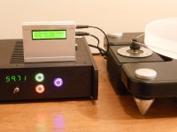
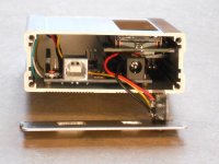
Finally got all the parts for the tach and was able to put it together in a 4" x 3" x 1 1/8" aluminum case that I bought on ebay several years ago for $5 IIRC. I had to remove the analog and power header on the Arduino PCB and I pressed some 2-56 x .125" standoffs into the mounting holes on the Arduino. The Uno mounts to the back of the enclosure with 4 pcs of 2-56 x 1/4" screws.
I drilled and filed a rectangular opening in the front of the enclosure and press fit a 1/16" thick smoke plexiglass window into the opening. The LCD display is then super-glued onto the inside wall of the case, centered in the window.
I ordered the hall sensor PCB from oshpark and attached it to the plinth with double sided foam tape. It seems to work very well.
Attachments
- Home
- Source & Line
- Analogue Source
- Digital Tachometer for record player (LCD display)