Hi.
To Packgrog : Another way that I tried was using a counter. When the first interrupt occurred start to count until the second interrupt then divide it for how long the micro take to execute an add instruction. It came very close but using the micro was more easy. Do you use the Mouser sensor or the cheap one?
To Packgrog : Another way that I tried was using a counter. When the first interrupt occurred start to count until the second interrupt then divide it for how long the micro take to execute an add instruction. It came very close but using the micro was more easy. Do you use the Mouser sensor or the cheap one?
Hello guys,
Mind if I join in? I was very interested in this project and had to build one. I'm a total newbie to Arduino Uno and coding.
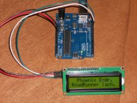
Credit goes to you guys who published the code as a base for me to achieve something here. I bought a Midas LCD display (which I like the high product quality) and for some reason I cannot interface it with a common I2C serial adapter which I'm reckoning there's some compatibility issue. I nearly fried them in the process as 1 chip got behind the lcd got very hot and fortunately its still working. At the end I've to wire it up in conventional parallel mode. This is the result after a week of doing it.
https://www.youtube.com/watch?v=LkcOGgYI6Uk
Mind if I join in? I was very interested in this project and had to build one. I'm a total newbie to Arduino Uno and coding.
Credit goes to you guys who published the code as a base for me to achieve something here. I bought a Midas LCD display (which I like the high product quality) and for some reason I cannot interface it with a common I2C serial adapter which I'm reckoning there's some compatibility issue. I nearly fried them in the process as 1 chip got behind the lcd got very hot and fortunately its still working. At the end I've to wire it up in conventional parallel mode. This is the result after a week of doing it.
https://www.youtube.com/watch?v=LkcOGgYI6Uk
Hello guys,
Mind if I join in? I was very interested in this project and had to build one. I'm a total newbie to Arduino Uno and coding.
Credit goes to you guys who published the code as a base for me to achieve something here. I bought a Midas LCD display (which I like the high product quality) and for some reason I cannot interface it with a common I2C serial adapter which I'm reckoning there's some compatibility issue. I nearly fried them in the process as 1 chip got behind the lcd got very hot and fortunately its still working. At the end I've to wire it up in conventional parallel mode. This is the result after a week of doing it.
https://www.youtube.com/watch?v=LkcOGgYI6Uk
I just received my Uno R3 and an I2C LCD board from a vendor on e-Bay. No documentation at all on either one. I tried the Arduino example file "LiquidCrystal_PCF8574"; nothing, stone dead. Fortunately, I know a fair amount about these LCDs (for 20+ years, I've been writing assembly code for LCD displays from 1x8 char modules up to 320x240 graphic displays) so searching the web for ~4 hours, I was able to uncover a number of things. First off, when the display powers up, the first line should be all blocks (5x7 pixels for each char, all on, i.e. dark). The second line will be blank. Turn the pot on the I2C board until you see this character pattern on the display. Without the pot adjusted for the proper contrast, I saw absolutely nothing on the display, so even if it was working, you would have no way of knowing that.
Next on the list is connection to the Arduino. 5V and Gnd are self explanatory, but SDA and SCL are not. Most pages on the web that I uncovered had these to lines going to A4 and A5. On the Arduino reference libraries page, they list the standard library files that come with the IDE. Click on WIRE for a description of hardware connections to the I2C device (it varies with model and rev #). On the UNO R3, there are dedicated pins at the far left of the 18 pin header (left of ARef) as viewed with the USB connector on the left edge of the PCB. The pins are labeled SDA and SCL on the bottom PCB silk screen.
The e-Bay listing said the I2C address is factory set to 0x20 although it could be changed to any value between 0x20 and 0x27. Another paragraph said the factory setting was 0x27. Tried all 8 values still nothing. Got the data sheet for the 8574 and traced the connections on the PCB and used a voltmeter to determine the address. All address pins were HIGH which would indicate 0x27. Still nothing.
Time to get the DSO out and do some troubleshooting. Logged the logic states of both the SDA and SCL lines over one communication frame. Back to the data sheet. The address scheme looked right, 7 data bits, one R/W bit with the address set to 0x27. The master (UNO) sends the 9th clock pulse with the SDA high and looks for the slave (LCD) to pull the line low as an ACK. This was not happening. The data sheet shows two versions of the chip: PCF8574 and PCF8574A; the "A" version uses address 0x38-0x3F. With all the solder jumpers open, that should make my PCB address 0x3F.
Recompiled using this address and surprise, it worked. Only took about 6½ hours to get there. How on earth do you guys deal with this?
One thing I have yet to find, is a list of functions available in the PCF8574 version of the IDE library. The on-line reference only shows the standard (serial) library functions and I've already noticed some differences. The 8574 example file runs the LCD through its paces, so a lot of them are shown there. Anyone know where I can find a complete list?
Attachments
Anyone know where I can find a complete list?
Never mind, I think I just found it. LiquidCrystal_I2C.h has a function list, although the object creation syntax is different in the .h file from the example code. The syntax in the Arduino source file for my display looks like this:
LiquidCrystal_I2C lcd(0x3F); //* create object lcd with class LiquidCrystal_I2C and address 0x3F
lcd.begin(16,2); //* 16 chars x 2 lines
There is also an error in the PCF8574 datasheet. The address diagram shows a 7 bit address for the PCF8574, and an 8 bit address for the PCF8574A version. This is incorrect; they are both 7 bit addresses, the 8th bit is R/W for both devices.

Never mind, I think I just found it. LiquidCrystal_I2C.h has a function list, although the object creation syntax is different in the .h file from the example code. The syntax in the Arduino source file for my display looks like this:
LiquidCrystal_I2C lcd(0x3F); //* create object lcd with class LiquidCrystal_I2C and address 0x3F
lcd.begin(16,2); //* 16 chars x 2 lines
:
Hi Pyramid,
I learned a few things earlier about the I2C interface. Firstly, I've to know the I2C address before applying any subsequent code. I use I2C scanner code to scan the lcd (with backpack). I have 1 ("ebay type?") LCD's, A far more "expensive" Midas LCD and two I2C modules without documentation too, left to fend for myself to figure out. These 2 I2C modules although looking similar are configured different default address, (0x3F & 0x27).
Then I learned there's V1, V2 and other I2C modules that may have compatibility issues with certain LCD modules. Without much knowledge, I nearly fried my "expensive" Midas (brand) LCD using a V1 backpack module. I learned to remove the jumper otherwise I'd screw up the Midas LCD for sure. With the 2 pin jumper "on", one IC went hot. I had remove the jumper, put away the I2C module (no alphanumeric display but backlighting was ok) and wire it up in the normal parallel fashion.
I noted that this Midas LCD contrast pot is wired differently from those Ebay type LCD. Pin 3 (Vo) from LCD is wired to Pot Pin 2 slider. The other 2 (Vdd & Vee) connected to Pot Pin 1 &3. Only by this method that the contrast is can be nicely adjusted. If I had grounded the pin 3, the contrast adjustment was somewhat abnormal.
Forgive me if I sound naive or silly at times, I'm still learning and sharing my experiences.
Kind regards,
Lee
Last edited:
Hi,
That's why I used the serial Newhaven lcd display. Do not need library just wire it to the IDE serial output monitor or the TX output pin in the Arduino Uno. You can use the Arduino Serial.print command. The only problem it is pricey $23.00.
Mouser Part number: 763-0216S3ZFLGBW-V3 for the 2x16.
That's why I used the serial Newhaven lcd display. Do not need library just wire it to the IDE serial output monitor or the TX output pin in the Arduino Uno. You can use the Arduino Serial.print command. The only problem it is pricey $23.00.
Mouser Part number: 763-0216S3ZFLGBW-V3 for the 2x16.
Hi,
That's why I used the serial Newhaven lcd display. Do not need library just wire it to the IDE serial output monitor or the TX output pin in the Arduino Uno. You can use the Arduino Serial.print command. The only problem it is pricey $23.00.
Mouser Part number: 763-0216S3ZFLGBW-V3 for the 2x16.
That would undoubtedly been easier and if I knew what a debacle using the I2C was going to be, I might have done it, although it's nice to keep the serial port open for communication with the PSU without having to bit-bang it on another output pin and write 9600 baud delay routines.
The I2C board and LCD were only $6.75 on Flea-Bay. Add 6½ hours (@$75.00/hr engineering time), and it only cost me $456.75. Cheap!😀
Hi Pyramid,
Yesterday, I was reading your post #124 and didn't quite understand. I'm unsure if the problem was similar. I said I have a cheap LCD with serial backpack and couldn't get it to display anything, even on a simple routine like "Hello World", The LED backlight would light up and nothing displayed and continuously flash. I thought of 2 things, either the thing is bust or something isn't right with the code. I had intended to get an exchange soon.
Today, I spent time researching and trying to find a solution. While reading trouble shooting hints from various sites, I found this page with more info on various cards.
https://arduino-info.wikispaces.com/LCD-Blue-I2C
To get it to work, Line 3 may have to be altered to suit the I2C adapter model or type. This is where it wasn't apparent and entirely oblivious to me at this point.
I also had to download and add in Wire.h & LiquidCrystal_I2C.h zip/library.
======================================
#include <Wire.h>
#include <LiquidCrystal_I2C.h>
LiquidCrystal_I2C lcd(0x3F, 2, 1, 0, 4, 5, 6, 7, 3, POSITIVE); // Set the LCD I2C address
======================================
I've seen a number of different address and sequence variation.
I've now got this lcd to work very nicely with the tachometer code and I don't have to make a tedious trip to get an exchange. Phew!
I'm also in the process of trimming down unnecessary lines and comments for least memory used. I think I saw up to 20% memory space used for the original tachometer code.
Last edited:
LMAO! Cheaper than trying to get a proper Roadrunner or Falcon these days! 😛The I2C board and LCD were only $6.75 on Flea-Bay. Add 6½ hours (@$75.00/hr engineering time), and it only cost me $456.75. Cheap!😀
Odd that wiring up the basic LCD without I2C board would turn out to be easier. It's certainly uglier. I do have another one (the one tauro0221 linked) on the way to me eventually, so that I can clean up the wiring. Sounds like the code will be a PITA, though.
On a diverging side note, I tried doing the silk thread belt trick yesterday, which I've never been able to do without a proper tach. The Falcon adjusted the speed up from about 30.0 RPM in less than a minute, and held steady (so I think the tach code is as optimized as I can get it). I did notice a LOT more background noise at first, until I placed my hand on top of the motor pod. So now I have the ghetto-tastic hack of a ziplock snack bag filled with playground sand on top of my motor pod to increase the contact force with the Herbie's Tenderfeet (I might go back to the small diameter thick grungebuster dots, though, which are now under the tiptoe feet), and dampen some of the ringing in the top plate of the motor pod. Not that I want to stir up more of the Phoenix vs. VPI sh*tstorm, but it does strike me as an odd design choice to have parts of a motor pod able to ring like a bell even when tapped with a finger. Is this being exacerbated by the sinewave phase when the Falcon boosts the speed from 30 to 33 RPM (with 30 being reached at about 60.1Hz)? Or is that vibration level always there, and just more noticeable when switching from a more compliant rubber belt to a less compliant silk thread belt?
(I really don't want to go down an anti-VPI rabbit hole, BTW, I just want to address some issues that I may be making worse with my custom usage)
Removing comments is not recommended. It should make no difference on the memory space usage (unless the compiler is crap). When compiled, comment lines should be ignored.I'm also in the process of trimming down unnecessary lines and comments for least memory used. I think I saw up to 20% memory space used for the original tachometer code.
As far as my codebase, the only thing you could safely remove is the Serial calls, as they would do nothing for you UNLESS you were running it on USB power and wanted to verify that what's output to Serial is roughly the same as what the LCD is displaying. As stated before, it should make little difference to the interrupt timing.
Removing comments is not recommended. It should make no difference on the memory space usage (unless the compiler is crap). When compiled, comment lines should be ignored.
As far as my codebase, the only thing you could safely remove is the Serial calls, as they would do nothing for you UNLESS you were running it on USB power and wanted to verify that what's output to Serial is roughly the same as what the LCD is displaying. As stated before, it should make little difference to the interrupt timing.
Hi,
Noted your comments with thanks 🙂
I removed the last part:
-------------------------------------
// Send update to Phoenix PSU via serial port (D0 and D1) in format XX.XXX[lf][cr]
if ((10.0 <= rpm) && (rpm < 100.0)) {
char outstr[8];
dtostrf(rpm, 6, 3, outstr);
outstr[6] = '\n';
outstr[7] = '\r';
//Serial.print(outstr);
}
-------------------------------------
On another note, I experimented with this: Changed sensor pin to Pin 2 or 3 and alter this line to correspond assigned pin. Either will work fine. Yes, also noted that its only these 2 pins with interrupt address.
#define SENSOR_PIN 3 // Interrupt input pin for sensor on Arduino UNO MUST be pin 3.
I also customed the 2nd row display to " < Ready> flash flash < STOP >. Just fooling around.
-------------------------------------
lcd.setCursor(0, 1); // Set cursor at first character, second line.
lcd.print(" < Ready > ");
delay(500);
lcd.setCursor(0, 1);
lcd.print(" ");
delay(500);
cycle_count = 1;
lcd.setCursor(0, 1);
lcd.print(" ");
delay(500);
lcd.setCursor(0, 1);
lcd.print(" < STOP > ");
cycle_count = 0;
}
--------------------------------------
Last edited:
You can comment out (or simply remove) the entire block starting with "if ((10.0 <= rpm) && (rpm < 100.0))". Also remove "Serial.begin(9600); " from the setup function.
I'm not sure I understand what you're trying to accomplish with your LCD output, though.
I'm not sure I understand what you're trying to accomplish with your LCD output, though.
Sounds like the code will be a PITA, though.
I think it is all sorted out now. If you're unsure about the address, I think someone else posted that the IDE comes with an example called Scanner; it accesses the I2C bus, pings all 127 addresses and reports which ones answer (ACK) in the serial monitor window. If I would have done this, I probably could've saved a lot of time, but I felt like I was working with blinders on.
Not that I want to stir up more of the Phoenix vs. VPI sh*tstorm, but it does strike me as an odd design choice to have parts of a motor pod able to ring like a bell even when tapped with a finger. Is this being exacerbated by the sinewave phase when the Falcon boosts the speed from 30 to 33 RPM (with 30 being reached at about 60.1Hz)? Or is that vibration level always there, and just more noticeable when switching from a more compliant rubber belt to a less compliant silk thread belt?
Not sure. The motor's main vibration response is at Fr x 2, where Fr is the drive frequency. The measurements I posted on the VPI Forum were done at 60Hz (wall power). It would be odd if the motor housing has a greater response at 60.1Hz than it has at 60Hz, so I don't think it is the drive frequency that is exciting the top plate with your new set up. It may be some combination of the variables: belt, tension, plinth, platter or bearing that are making the difference. This is one of the reasons why I measured the motor by itself to get a baseline reading of the vibration generator without any outside influence. If you want to test this theory, measure the vibrations at 60Hz vs 60.1Hz with no belt and the vibrations at 60.1Hz with no belt and 60.1Hz with belt.
Let us know what you find....
Hmmm... Interesting point. I have a VibroMeter app on my iPhone that MIGHT help, though the weight of the phone itself might dampen the vibrations to the point of messing with the numbers. Would probably be better to use a vibration sensor and the Arduino. How's that for a weird irony? 😛If you want to test this theory, measure the vibrations at 60Hz vs 60.1Hz with no belt and the vibrations at 60.1Hz with no belt and 60.1Hz with belt.
I remember stumbling across this thread a while back, and I might try something like the Walker Audio resonance control discs ON TOP of the motor pod rather than inside on the base plate, since the vibration is all coming from the top plate. But those things are also crazy expensive ($50 each!?), and I'm getting off topic.
Getting back *ON* topic, I did notice that eventually the tach stopped updating. I had it on for a couple of hours. Not sure what the problem was. I powered it off and back on, and all was normal again. Weird.
Getting back *ON* topic, I did notice that eventually the tach stopped updating. I had it on for a couple of hours. Not sure what the problem was. I powered it off and back on, and all was normal again. Weird.
If it happens at ~71 minutes after being powered on, it is probably caused by the way you are using the micros() function. They keep track of the count in an unsigned long variable (32 bit) that increments every 4µSec so it will give an erroneous result every 1 hr, 11 min and 35 secs (negative result when you do next_reading=micros()-last_reading). You trap the display of this result with your if(micros()>last_reading) statement, since this will fail when that happens, but I don't know if you reset last_reading after the roll-over, so it will fail continuously after that.
FYI, the way you compute delays with millis() will also fail (for the same reason), but it will take almost 50 days for it to happen.
Ah yes. I only do "prev_pulse_time = last_pulse_time" when "last_pulse_time > prev_pulse_time". Not a graceful handling of the overflow. Oops. Ah well. Easy fix next time I tear it apart. I should also find a more graceful way of setting the " RPM: " text for when the platter is already spinning on startup.
One other side note that I discovered (after damping the hell out of the motor pod and switching back to the stock belt): Making sure that the pulley and platter grooves line up makes a big difference for speed bobble.
Long-winded explanation: I use Herbie's Audio Labs extra-thick grungebuster dots (small diameter) as replacement feet for the motor pod. It improves the sound thanks to better vibration handling, but also lowers the motor substantially. I would not be able to play records at 45RPM without the motor controller due to the height difference. Putting the belt on the bottom 33 groove of the pulley lines the belt up with the lowest grooves on the platter.
When placing the belt on the platter, it tends to stay in higher grooves until the motor is started, then it pulls itself down to closer to the pulley's level. The furthest it shifted on its own was to the next-to-last platter groove, which puts the belt at an awkward angle to the preferred pulley groove. This caused the tach to display very significant fluctuations in the speed, and the Falcon was re-adjusting constantly. I then bumped the belt down to the bottom platter groove (which lines up better with the pulley groove), and the bobble reduced significantly and stayed fairly stable, with the Falcon adjusting far less frequently.
Fun little things that never would have occurred to you without unusual measurement tools!
I've been playing with the Uno for a couple of days now and think I have a tach version very close to the RoadRunner.
It uses the timer2 interrupt to generate a 16 bit count. The timer resolution is 32µSec, so the display is only 3 digits right of the decimal. In order to have a stable count, I had to disable Timer0 which is used by the Uno OS for millis(), micros() and delay(), so do not call these routines or the board will get hung endlessly as these routines no longer function. If you must use a delay, use delayMicroseconds() as this does not use timer0; because of the timer2 overhead, divide the expected value by 3 (delayMicroseconds(50) produces a 150mSec delay). You can also use the built in mSec delay. The global variable MSEC is incremented every 992µSec by the Timer2 interrupt routine and can be used to measure time in mSec.
I toggle PB2 (digital output 2) everytime the Timer2 ISR fires. If Timer 2 is interrupting at exactly 32.000µSec, the output at pin 2 would be 15,625 Hz and RPM would equal to: 1,875,000/COUNT. Because there is a slight overhead in the ISR response time, timer 2 is running at ~32.02µSec so the numerator has to be adjusted. This is stored in the source file as constant CALIBRATE and should be equal to the frequency at PB2 x 120. You can also tweak this number in small amounts to offset any frequency error of the crystal.
The LCD routines use I2C interface, so you will have to adapt them if using serial or parallel interfaces (some of the syntax varies between control methods). The tach will flash a disc icon whenever the sensor trigger is active; the icon will be displayed for a minimum of 250mSec and will remain on as long as the sensor is active (useful for manually testing the sensor). If no trigger is received for ~2.5Sec, the reading is blanked (--.---).
I used the Hall Effect sensor from the RR and the display tracked very close to the RoadRunner tach display. You can build your own sensor using this PCB: RoadRunner Sensor PCB
The tach will also average the display reading (the serial data to the PSU is not and SHOULD NOT be averaged) if constant AVERAGE=true. If you don't want averaging, set this constant to false. You can also change the number of readings that are averaged; practical values are 2-8. The tach will not average the display for the 1st 16 readings in order to fill the array with stable readings. The built-in LED will be illuminated when averaging is applied. The 16 reading count is reset when the platter stops.
Video of the basic operation (I turned the backlight off as it washed out the display): Arduino Uno Tach
Code:
//* Uses I2C LCD interface.  SDA and SCL left most pins on 18pin header next to AREF
//* Check I2C address using Scanner example file; address range 0x20-0x27 and 0x38-0x3f.
//* RPM is computed using COUNT developed in Timer2 interupt @ 32µSec rate.
//* Timer0 is disabled so delay(), millis() and micros() will no longer function (hangs the UNO).
//* RPM calculation is: CALIBRATE/COUNT.  CALIBRATE=freq at digital pin 2 (PB2) x 120
//* At timer2 = 32.000 µSec, PB2 should be 15,625 Hz and CALIBRATE should be 1,875,000.
//* If AVERAGE=true, display data will be averaged MAX_AVG times. Pratical MAX_AVG values: 2-8
//* Set AVERAGE to false to disable averaging.
//* DO NOT average the data going to the PSU on serial port.

#include <Wire.h>
#include <LiquidCrystal_PCF8574.h>

LiquidCrystal_PCF8574 lcd(0x3f);

const int TRIGGER=3;            //* input on PB3
const float CALIBRATE=1873440;  //*equals freq @ PB2 x 120
const byte MAX_AVG=8;           //* set # of averages
const boolean AVERAGE=true;     //* set to false to disable averaging

unsigned int COUNT, RPM_COUNT=0;
unsigned long MSEC=0, ACTIVITY=0;
byte MS_PRESCALE=0, AVG_IDX=0, AVG_COUNT=0;
float RPM, AVG[MAX_AVG], TOTAL;
byte DISC[8]={B00000,B01110,B11111,B11011,B11111,B01110,B00000,B00000};   //* LCD custom char

boolean UPDATE=false, DONE=true, STOPPED=true;


// the setup function runs once when you press reset or power the board
void setup()
{ Serial.begin(9600);
  pinMode(LED_BUILTIN, OUTPUT);
  pinMode(2,OUTPUT);                    //* Calibrate output
  pinMode(TRIGGER,INPUT_PULLUP);        //* PB3 trigger input

  TCCR2A=0x02;    //* CTC mode
  TCCR2B=0x04;    //* ÷64 Prescalar
  TCNT2=0;
  OCR2A=7;        //* 32µSec rate
  TIMSK2=2;       //* enable OCR2A interrupts
  TIMSK0=0;       //* disable timer0 interrupts

  lcd.begin(16,2);
  lcd.createChar(0,DISC);
  lcd.home();
  lcd.clear();
  lcd.setCursor(0,0);
  lcd.print("Arduino Uno Tach");
  lcd.setCursor(0,1);
  lcd.print("RPM: --.---");
  lcd.setBacklight(255);
}

// the loop function runs over and over again forever
void loop()
  {
    if(UPDATE && DONE)
    { RPM=CALIBRATE/RPM_COUNT;      //* compute RPM
      if(RPM>28 && RPM<100)
      { Serial.print(RPM,3);        //* Dont average the serial data
        Serial.print('\n');
        Serial.print('\r');
        if(AVERAGE)                 //* check if we are averaging
        { AVG[AVG_IDX++]=RPM;       //* save current value in circular queue and move pointer
          if(AVG_IDX==MAX_AVG)      //* check for overflow
            AVG_IDX=0;              //* yes, reset pointer to beginning of queue
          if(AVG_COUNT==16)         //* Don't display average for at least 16 readings
          { TOTAL=0;
            for(int x=0; x<MAX_AVG; x++)  //* Recompute RPM as average of last MAX_AVG readings
              TOTAL+=AVG[x];
            RPM=TOTAL/MAX_AVG;
            digitalWrite(LED_BUILTIN,HIGH);
          }
          else
            AVG_COUNT++;            //* leave RPM as is, increment count
        }
        lcd.setCursor(5,1);
        lcd.print("           ");
        lcd.setCursor(5,1);
        lcd.print(RPM,3);
      }
      DONE=false;                       //* reset trigger flag
      STOPPED=false;                    //* platter turning,reset flag
      ACTIVITY=MSEC;                    //* Start Activity timer
      lcd.setCursor(14,1);              //* display DISC Icon
      lcd.print(char(0));
      mydelay(250);                     //* for at least 250mSec
    }
    if(!DONE)
      if(digitalRead(TRIGGER)==HIGH)    //* check for no trigger input
      { UPDATE=false;                   //*reset for interrupt routine
        DONE=true;
        lcd.setCursor(14,1);            //* turn off Icon
        lcd.write(byte(32));
        mydelay(50);
      }
    if(!STOPPED)
      if(MSEC-ACTIVITY>2500)            //* check if platter stopped
      { STOPPED=true;                   //* yes, flag it
        lcd.setCursor(5,1);             //* blank reading
        lcd.print("--.---");
        AVG_COUNT=0;                    //* reset average count
        digitalWrite(LED_BUILTIN,LOW);
      }
  }

void mydelay(int TIME)    //* range 1mSec to 65.535 Sec.
{
  for(int x=0; x<TIME; x++)
    delayMicroseconds(300);
}


ISR(TIMER2_COMPA_vect)  //* timer 2 interrupt: 32µS rate 8 bit auto reload
{ COUNT++;
  digitalWrite(2,!digitalRead(2));    //* Toggle TP PB2
  if(digitalRead(TRIGGER)==LOW && !UPDATE)
  { RPM_COUNT=COUNT;                  //* capture value
    COUNT=0;                          //* reset counter
    UPDATE=true;                      //* flag for main routine
  }

  if(++MS_PRESCALE==31)               //* check for msec update
  { MS_PRESCALE=0;                    //* reset counter
    MSEC++;                           //* increment msec count
  }
}
Attachments
Woah! Digging deep into lower level stuff that I even thought to look for. Nice!
There's a lot more assignment going on in your interrupt handler. Is this less of an issue for delays due to the use of the higher priority timer and lower level interrupt handling?
Are you actually using digital pin 2? I'm a little lost on the "pinMode(2,OUTPUT);" line. I currently have that pin attached to my LCD with the crazy wiring, but could easily shift it up. Of course this may be moot once my own I2C LCD shows up. (EDIT: I see your comment above)
Funny how all of the threads I encountered about float values not printing properly with "Serial.print(RPM);" never once mentioned using the second parameter as in "Serial.print(RPM,3);".
Fascinating. Thanks very much for sharing this! I'll try to adjust for my own LCD and give it a try soon.
Last edited:
- Home
- Source & Line
- Analogue Source
- Digital Tachometer for record player (LCD display)