And there are punters who are quick to roll these out and swap them for newer parts.
I've always been a fan of the 5534 and 5532.
Nothing wrong with the 5532 or 5534
") , except that they can be a bit power hungry.
, except that they can be a bit power hungry.These days there are alternatives that perform similar, but with lower power.
There are also other situations that they are just not ideal.
In the end a lot again depends on context, raw performance and distortion numbers don't always show that.
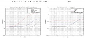
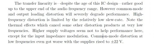
....shows the 5532 distortion worsening markedly at lower load impedances. Your driving just under 1k for most of your opamps and yet your results are spectacular.
I thought '5532 was fine to 600Ω?
While the chip makers *could* own SOTA meters, I think few do, or use them. Audio is still a niche market. And nothing you say will sway the few buyers, all of whom prefer to DIY their evaluations.
Mark's technique of cascading is certainly a reasonable simplification of modern studio audio paths. Whether Mark is making some mistake in reading, I can't say.
Sandy Todorov has made some measurements of THD on NE5534.
They are to be taken with a pinch of salt, but they interesting:
low Distortion Oscillator GS 5534-8 (NE5534)
With some opamp types, and in some conditions (increased loading, but not too heavy), I have noticed counterintitive effects:
A good unbalancer suggestion?
I have no definitive explanation for the effect.
From what I can make out that's in agreement, with gain of -1 and lightly loaded the values seem to be 1ppm or so.Sandy Todorov has made some measurements of THD on NE5534.
They are to be taken with a pinch of salt, but they interesting:
low Distortion Oscillator GS 5534-8 (NE5534)
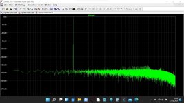
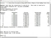
Going to heavier loads or very high signal levels or higher frequencies will quickly take its toll too I'm sure, but a few volts at 1kHz with inverting topology the 553X seems to be at the top of its game. I was using +/-9V battery supplies BTW.
One thing puzzles me in tests such as these and its this...
Manufacturers of high performance opamps often give distortion figures magnitudes more than the levels these kind of test set ups (in this thread) show. Not only that, but the manufacturers (who it must be assumed have absolutely state of the art measuring techniques and equipment) also state that the performance of the opamp exceeds currently availbale measuring equipment.
A typical statement from a data sheet would be:
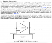
The special test circuit referred to is the trick of increasing noise gain by the addition of a single resistor per stage.
There's a good description of the "trick" circuit in the LME49720 data sheet. I've attached it here. It's from page 24 of the LME49720 data sheet.
There's nothing secretive or occult about this. The circuit lowers the loop gain by a factor of 100 (40 dB). It is assumed that this increases the distortion by 40 dB as well. So you simply subtract 40 dB from the measured value and you have the actual distortion.
This assumption relies on the fact that any error introduced within the loop of a feedback system is reduced by a factor equal to the loop gain. So if you lower the loop gain by 100x you get 100x less reduction of the distortion, hence, measure 100x the actual value. This can be proven mathematically. It's actually fairly straightforward, but since I don't have the proof committed to memory, I refer you to Franco, "Design With Operational Amplifiers and Analog Integrated Circuits" if you're interested. The assumption also relies on the majority of the distortion being introduced within the loop; so within the opamp and not by, say, an input clamp or ESD structure.
I'm curious why the circuit of 10 opamps in series was chosen here over the measurement circuit used by TI and others.
Tom
Attachments
12 opamps - I guess really to provide good evidence that lots of cheap opamps in the audio processing chain are fine and dandy. The behaviour when abused (slew-limiting, post #62) is interesting as it tends to escalate down the chain which shows the importance of avoiding slew-limiting.I'm curious why the circuit of 10 opamps in series was chosen here over the measurement circuit used by TI and others.
But really the reason is I wanted to build an opamp array amp, but the good price-break for NE5532DR's was at 100 units, so I have plenty left over to experiment with. So cheap in fact I think the thin-film resistors on that pcb might have been more costly than the opamps!
One caveat, distortion harmonic components are vectors, not scalars. They do not simply add, but a considerable amount of cancellations may occur. For 12 op amp stages in series, the process is impossible to control or reproduce, since there are no two identical op amps. A Monte Carlo simulation could reveal something interesting, the problem is equivalent with the Drunkard’s Walk problem (what is the most probable distance a drunkard will find himself from the starting point after N steps with Pi i=1…N probabilities?), which is a Wiener process, or more general a non-Markov random process characterized by stochastic integral equations (it’s actually simpler than it sounds).
So the relationship between the distortions of 12 stages in series and the distortion of an op amp is weak. I don’t think the result of 12 stages has much of a practical interest in audio. It could be used as a SPC in op amp manufacturing QA, though.
So the relationship between the distortions of 12 stages in series and the distortion of an op amp is weak. I don’t think the result of 12 stages has much of a practical interest in audio. It could be used as a SPC in op amp manufacturing QA, though.
Last edited:
A Monte Carlo simulation [...]
...assuming distortion is even included in the opamp model. I agree wholeheartedly otherwise, though.
Tom
I have been following it all even if I haven't said much
Thanks Tom. Quite a few data sheets show and mention the noise gain trick which is where I first became aware of it.
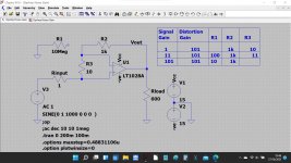
Somehow, I don't think it is, at least not the ones I've tried. This is a sim I put together a few years ago.
There's a good description of the "trick" circuit in the LME49720 data sheet. I've attached it here. It's from page 24 of the LME49720 data sheet.
Thanks Tom. Quite a few data sheets show and mention the noise gain trick which is where I first became aware of it.
...assuming distortion is even included in the opamp model. I agree wholeheartedly otherwise, though.
Tom
Somehow, I don't think it is, at least not the ones I've tried. This is a sim I put together a few years ago.
Attachments
One caveat, distortion harmonic components are vectors, not scalars. They do not simply add, but a considerable amount of cancellations may occur. For 12 op amp stages in series, the process is impossible to control or reproduce, since there are no two identical op amps.
I'm sceptical about this in this situation.
All the opamps are identical (*), consecutive from the same reel (so likely from the same wafer), so I suspect they are very similar in distortion behaviour.
Usually you'd expect low frequency distortion (where stray impedance variations won't matter and phase shifts are tiny) to be due to a repeatable (slightly) non-linear transfer function, and repeatedly applying the same function (for signal at the same amplitude) will cumulatively increase each harmonic distortion component in proportion to the number of steps, provided the components are small.
The multi-stage inversion circuit only does this for odd harmonics though and alternate stages should cancel even harmonic distortions.
Distortion cancellation requires different transfer functions to be applied successively, and outside of this inversion cancellation of even harmonics that means different components at each stage (such as DAC, amp, ADC, where there will likely be 3 different transfer functions).
(*) my caveat about this is that the two copies on each die might not be strictly identical to each other, especially as this is such a venerable chip design which may even have been laid-out by hand originally.
Distortion cancellation requires different transfer functions to be applied successively, and outside of this inversion cancellation of even harmonics that means different components at each stage (such as DAC, amp, ADC, where there will likely be 3 different transfer functions).
I'm afraid is not that simple. Since we are talking non linear here, the superposition theorem (allowing to apply successively transfer functions) doesn't apply. Once again, there's not much we can do other than relying on statistical modelling (which could be parametrized by assigning a distortion probability distribution).
Somehow, I don't think it is, at least not the ones I've tried. This is a sim I put together a few years ago.
I am not aware of any audio grade op amp model that has distortions included, other than LM4562, LME49710 and their kin (same silicon). It's a device level model, compared to the common behavioral op amp models that almost never include the dynamic non linear behavior. The behavioral models are accurate for DC and AC simulation, but may provide very poor/misleading results for TRAN.
The point is when the distortion components are small, their interactions are even smaller and can be ignored, so you can assume that things build up cumulatively to a first approximation.
Take the function f(x) = x + 0.001 x^2
f(f(x)) = x + 0.002 x^2 + 0.000002 x^3 + 0.000000001 x^4
Distortion has to be quite gross before this breaks down.
Take the function f(x) = x + 0.001 x^2
f(f(x)) = x + 0.002 x^2 + 0.000002 x^3 + 0.000000001 x^4
Distortion has to be quite gross before this breaks down.
I’m sorry, I don’t follow your logic. You cannot treat distortions like small perturbation, since that assumes they are independent variables, which they are obviously not; independent means no cancellation occurs (but only addition), which is absurd. You can’t have the cake and eat it too.
Its a simple 2nd order distorting transfer function applied twice, how is that hard to follow?
The result is a 2nd order distorting transfer function if you ignore the higher order terms which are 1000 times smaller - my assertion is you can validly ignore those terms when the non-linearities are tiny, which they are.
Not there's not a hint of statistics here, the signals are not stochastic in any way.
Totally with Mark here. We can agree that:
1. the 11 inverting opamp stages are nearly identical
2. their input signals are nearly the same (with the distortions & noise added by previous stages being very small compared to the original signal)
3. hence their transfer functions should be nearly identical
We can always multiply their transfer functions, no matter how nonlinear they are and calculate HD afterwards.
In this case the are all the same and quite linear, so we can for once assume linear superposition of hte harmonics and thus safely assume that an indivdual stage contributes 1/11 of each harmonic.
- Home
- Source & Line
- Analog Line Level
- 12 opamps chained - measurements