@hellokitty
I have a busy day today, so I cannot yet respond the way I should. But my first reaction is that I do not understand your noise spectra. An EC does not see the difference between noise or distortion coming from the main amp, so both will be corrected to a level depending how strong the EC suppresses these anomalies.
Since your EC is supposed to suppress very strong, I would expect to see just the same EC generated noise from your Sims in all the end results and nothing else, no matter whether the gain is 1x or 10x an no matter whether the 10 Ohm between the input of the LT1364 is inserted or not. Since your noise spectra are telling a different story, I'm not yet confident the EC is already working properly at the moment.
Tonight I will show you with Sims what I'm trying to tell you.
Hans
I agree 100%. The ideal op amp is a pretty useless idea that can lead to paradoxes if not non sense. Bogus science, we have enough on diy. The right way is: An Op amp is an amp with very large gain, large input impedance, small output impedance.Ahh yes, I was assuming a real-world opamp.
Jan
The ideal op amp is a pretty useless idea that can lead to paradoxes if not non sense. Bogus science, we have enough on diy.
Not at all, it is a very useful idea to understand the workings of a circuit. Using an ideal opamp idea, infinite gain, zero output R, infinite input R, is quite useful to understand a specific concept.
Jan
I disagree entirely with mchambin. I certainly wouldn't want to accuse professor Bernard Tellegen (inventor of the pentode, the gyrator and of the ideal element that was later renamed to nullor) of bogus science. Besides, conceptual thinking and using different levels of abstraction really helps me to get more insight into circuits, and sometimes leads to configurations I wouldn't have thought of otherwise.
A nullor (nullator-norator pair) is the most ideal and most abstract model for the active part of a feedback amplifier; if you can't even get something to work as intended with a nullor as active part, chances are it certainly won't work when all imperfections of a real op-amp are included. Of course less abstract models also have their merits, once you figured out something could work in principle if only you had a nullor at your disposal.
A nullor (nullator-norator pair) is the most ideal and most abstract model for the active part of a feedback amplifier; if you can't even get something to work as intended with a nullor as active part, chances are it certainly won't work when all imperfections of a real op-amp are included. Of course less abstract models also have their merits, once you figured out something could work in principle if only you had a nullor at your disposal.
I can imagine that if you are a diy-er building existing circuits you don't have a big need for such abstracts.
The nullator is a powerful concept, but I myself don't use it. I think it depends on what you grow up with.
Jan
The nullator is a powerful concept, but I myself don't use it. I think it depends on what you grow up with.
Jan
I think thinking in extremes is a key tool to coming up with new concepts and understanding some old ones. The last thing you want is variables of an imperfect device interfering with your conceptual results.
But on the flip side knowing the imperfect variables is needed eventually otherwise it won't work in reality, or you end up where I am now, not knowing what is true.
But on the flip side knowing the imperfect variables is needed eventually otherwise it won't work in reality, or you end up where I am now, not knowing what is true.
Last edited:
Keep going with concepts like infinity times zero, a sure way that leads to paradoxes, if not non sense. May be, to grasp this, needs the right knowledge in maths, sorry about that. Limits and convergence are not easy maths. Handwayving with these gives quick results...or plain failure when things become serious. As said, it all depends of what you grew up with. 😉
Limits and convergence are not easy maths. Handwayving with these gives quick results...or plain failure when things become serious.
That's why one should not resort to handwaving if one doesn't understand the issue ;-)
Unfortunately, handwaving is often used to camouflage such lack of knowledge.
Jan
Getting back to the second-order effects that are likely to limit the achievable distortion, I looked up the Cherry paper:
Edward M. Cherry, "A new distortion mechanism in class B amplifiers", Journal of the Audio Engineering Society, volume 29, number 5, May 1981, pages 327 and 328
Suppose there is a mutual inductance M between the loop from the positive supply through the output stage to the negative supply and back and the loop from the amplifier's output to the loudspeaker and back. Cherry calculates that for a class-B amplifier with 8 ohm load, this will theoretically result in a second order distortion of 3.333... ppm per nanohenry of mutual inductance at 10 kHz, or 0.3333... ppm/nH at 1 kHz.
It gets worse by a factor equal to the amplifier's voltage gain when the mutual inductance is between the loop from the positive supply through the output stage to the negative supply and back and the amplifier's input. So for a voltage gain of 30, that would amount to 100 ppm/nH at 10 kHz and 10 ppm/nH at 1 kHz (*).
This quote is quite interesting:
"For what the statistic is worth, in a group of fifty 50-W 8-ohm power amplifiers built to the same circuit but with different layouts, the median second-harmonic distortion of 10 kHz was about 30 ppm, and five (10%) had 100 ppm or higher. The amplifiers were constructed by electronics engineers who had been alerted to the problem and took common-sense precautions like twisting wire pairs that carried forward and return currents."
So all in all, to keep this effect below -290 dB second harmonic distortion at 1 kHz, you would need to keep the mutual inductance to the output circuit below 9.4868 aH and the mutual inductance to the input circuit below 9.4868 aH/Av, where Av is the closed-loop voltage gain (attributing the entire budget to one single mutual inductance and neglecting possible cancellation effects). You can look up mutual inductance equations to figure out what this means for the amplifier's layout, but I know from experience it is difficult to keep mutual inductances below a few picohenry.
Going for class A could help a lot, but still won't eliminate the effect. The distortion though each output device in a class A amplifier is much smaller than in a class B amplifier, but there is bound to be some distorted current flowing from the positive supply via the output stage to the negative supply. Maybe you can win a decade or two.
(*): For an integrated amplifier with moving coil input, he even estimates 0.33 % per nanohenry at 1 kHz for coupling into the moving coil input. The RIAA correction and the increase of the mutual impedance with frequency roughly cancel, so the same order of magnitude applies at other audio frequencies.
Last edited:
I typically try to stick to designs with symmetrical signal currents that cancel out. This is one of the benefits of that balanced operation easily allows. I would imagine that the overall effect of mutual inductance would be minimized in this scenario.
Last edited:
It depends. In a class-B bridge amplifier, the current from the power supply via the output stages to the other end of the supply would still be a rectified version of the signal. A balanced input can probably help to reduce mutual inductances, as you can twist the input wiring to get some cancellation. Using a single-ended class A output stage with current source biasing would probably be the best way to limit the distortion of the output device currents, but it is of course quite inefficient.
The bottom line is that second-order effects like this one and resistor nonlinearity will almost certainly increase the distortion to some value that may be quite low, but definitely much higher than -290 dB - which needn't be a disaster as long as the distortion is low enough for you to sell your amplifiers.
The bottom line is that second-order effects like this one and resistor nonlinearity will almost certainly increase the distortion to some value that may be quite low, but definitely much higher than -290 dB - which needn't be a disaster as long as the distortion is low enough for you to sell your amplifiers.
Would this be a good time to say that if someone says he can measure to -290dB then we may doubt him? I might take it seriously if someone from CERN or LIGO made such a claim, but almost everyone else (whatever their guru status) has to provide proof.
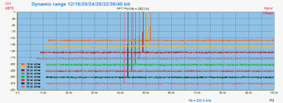
Some real digital generated signals using various bit sizes... 😀
Hp
Attachments
Well, obviously the noise floor itself is going to prevent the circuit from being any distortion beyond that. Regardless of anything else. I never claimed to be able to reduce noise floor below any point. My claim was that the circuit was capable of of reducing signal distortion down to -290db based on my tests and sims. Actually I'm pretty sure it can go further if the logic holds. However as it's been stated, I need to have a third party individual or lab confirm the results. I have limited money to spare so I'm holding back for a bit before I spend several hundred dollars on a prototype designed for critical testing.
infinity times zero, 0-, 0+, they are called limits, you can divide by 0+ and multiply by 0- etc if I recall, it is used to calculate convergence and extrapolate arithmetics and optimization.
infinity times zero is essential , I study fundamental maths at master level, the '0' was most of the studies haha. I got A+ in the course, I enjoyed study of such things as Brouwer fixed-point theorem. Definitions of spaces, decomposition of differential equations.. very cool.
Had to memorize this : Decomposition of ordinary differential equations | SpringerLink that wasted all my evenings back then.
Last edited:
Your time and money would be better spent learning why your claim is false, not trying and failing to show that it is true. In this thread various people have given you various reasons why you are mistaken, but in each case you have simply batted away their comments.
If someone claimed -180dB distortion we would look for an error in their arithmetic, or their experimental setup. We might be able to show them their error. Someone claiming -290dB distortion is simply announcing that they have not understood the problem; a more fundamental error than arithmetic or clumsy experiments. We probably cannot show them their error.
If someone claimed -180dB distortion we would look for an error in their arithmetic, or their experimental setup. We might be able to show them their error. Someone claiming -290dB distortion is simply announcing that they have not understood the problem; a more fundamental error than arithmetic or clumsy experiments. We probably cannot show them their error.
If you actually read through the thread, you would realize that is not true. I don't know why people continue to think I'm here to "prove" something. I'm only here to get to the truth, I've been laying it on pretty thick. My rebuttals are there with the intention of being corrected. If you don't correct me I don't learn. As far as I can tell I've made many counter points that have not been refuted if there is a refutation to be made as you say. If you don't refute my counter points I'm of course going to assume there is none. Lack of reading is a big problem in this thread.Your time and money would be better spent learning why your claim is false, not trying and failing to show that it is true. In this thread various people have given you various reasons why you are mistaken, but in each case you have simply batted away their comments.
I've given a huge amount of information on the circuit in question including measurement screenshots, test methodologies, and circuit diagrams, at least as far as I can go without sharing the schematic itself. If you have something to say about my logic and methodologies then you are free to say it.
Last edited:
Originally Posted by DF96 View Post
Your time and money would be better spent learning why your claim is false, not trying and failing to show that it is true. In this thread various people have given you various reasons why you are mistaken, but in each case you have simply batted away their comments.
If you actually read through the thread, you would realize that is not true.
I don't know why people continue to think I'm here to "prove" something.
If you don't refute my counter points I'm of course going to assume there is none.
Lack of reading is a big problem in this thread.
BIG problem here is that you have been shown errors or holes in your theories and you never ever acknowldge them.If you have something to say about my logic and methodologies then you are free to say it.
FROM THE VERY BEGINNING YOUR ILLOGIC CLAIMS HAVE BEEN MET:
You wrote post #1, these were the very first answers:
#2 :
You are probably fooling yourself
#4 :
These are phantom measurements.
#6 :
What??? -290dB distortion means a total of 3 femto volts harmonics to discriminate from noise. That means you either kept the DUT close to 0 Kelvin, or you spent years in auto correlating the signal from noise.
And so on and on and on and on and on ...........
Now you will say this is an incomplete sampling and you actually want the ~300 rebuttals?
What for? It´s useless preaching to the sea waves or the mountain echo.
This thread is a waste of time.
I didn´t want to reach this conclusion, for some time I believed your claim of needing confirmation to impress investors or something, but since that has long ago been proven impossible, and yet you insist, only alternative is that you are Trolling, pure and simple, and will hold on here for as long as somebody gets involved.
"Negative attention is better than no attention at all" ... at least for some.
Last edited:
In a class-B bridge amplifier, the current from the power supply via the output stages to the other end of the supply would still be a rectified version of the signal.
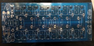
Marcel, this probably deserves a separate topic, but the magnetic effects of the half rectified power supply currents can be largely avoided by a clever PCB layout. Find attached such a layout I developed for a high power (up to 500W/4ohm) amplifier using Thermaltrak devices to compensate for temperature.
This is based on an idea from the same Cherry paper you quoted, where he suggested an "8" shape input stage layout to avoid magnetic effects. Here, the idea is to alternate npn and pnp devices and drag the +/- power supply lines through the middle of the PCB on both sides. This is equivalent to twisting the power supply lines straight from the power devices pins, the resulting external magnetic field being essential sinusoidal (much less harmonics than a full rectified sine), and I can vouch the practical results are nothing but spectacular compared to the standard layout with +/- supply lines each at the edge of the PCB.
As you can also see from the attached photo, the output trace takes the edges of the PCB, with the feedback pickup nicely placed at the current centroid.
Of course, this has nothing to do with -290dB distortions, but my result shows that such a layout can help not only in reducing the output stage magnetic distortions (such distortions cannot be in principle reduced by increasing the loop gain) but also making the whole problem of wiring a power amp much less critical.
I have no idea why such a layout was never employed in any commercial products (to the extend of my knowledge) since it is essentially a free method to improve performance. It probably doesn't sound good enough for the audiophiles 😀
Attachments
Nice layout! I read about Cherry's 8-shape, great that you managed to improve it further.
What kind of distortion do you achieve with this layout? Is the input balanced or single-ended? I presume the big capacitors are the power supply capacitors rather than local decoupling, is that correct?
What kind of distortion do you achieve with this layout? Is the input balanced or single-ended? I presume the big capacitors are the power supply capacitors rather than local decoupling, is that correct?
- Status
- Not open for further replies.
- Home
- Source & Line
- Analog Line Level
- -290 dB Distortion?