
Syn08, you've been mocking and insulting me for quite a while now. We get.
If my design is really so bad then it will be proven as such. Nothing to worry about. It's not like I'm asking for ways to trick people into believing unbelievable claims, which is part of the reason I despise the way the mod named this thread. You are not going to make me feel bad with your insults, sorry. I'm only interested in constructive conversation and getting to the truth. I think you are projecting arrogance onto my words instead of reading it for what it is.
If my design is really so bad then it will be proven as such. Nothing to worry about. It's not like I'm asking for ways to trick people into believing unbelievable claims, which is part of the reason I despise the way the mod named this thread. You are not going to make me feel bad with your insults, sorry. I'm only interested in constructive conversation and getting to the truth. I think you are projecting arrogance onto my words instead of reading it for what it is.
The part that confuses me is that I don't see a way to set the reference. So I don't know what the reference is. In any case dBr seems more useful than dBV if it works the way I think it does.Have you ever come across Wikipedia? I had never heard of dBr, and it turns out it just means dB i.e. relative to something. dBV, as I am sure you know, is dB relative to 1V. So one is a ratio and the other is a voltage. Does that help?
Last edited:
Getting back to the issue of resistor nonlinearity:
In his article in Linear Audio volume 1, the lowest-distortion resistors Ed Simon found, Dale RN65E S102 25 ppm/K military resistors, had third harmonic levels of about -170 dB with respect to the fundamental for a 1 kohm resistor with 7.905 V at 1 kHz across it. Third harmonic distortion goes up with the square of the signal voltage; that is, the third harmonic goes up with the third power and the fundamental with the first power, so the ratio goes up with the square. Hence, when you want to reduce the distortion to -290 dB, you can only allow 7.905 mV across each resistor.
As mentioned in post 245, you can cancel the distortion to some extent by using series strings of resistors of the same type and hoping that distortion matches. Wild-guessing that matching between the distortion of resistors of the same type is good enough to get somewhere between a factor of ten and 100 improvement, maybe you could allow something between 25 mV and 79.05 mV. All in all, between 358 and 3578 resistors in series for a 100 W in 8 ohm amplifier.
Unfortunately, Ed Simon also found second harmonic distortion. I don't really trust his second harmonic results because many very different resistors have values around -175 dB, but assuming that this is correct, you would need to back off the voltage per resistor to about 14 uV to reduce the second harmonic distortion to -290 dB, or maybe 140 uV...1.4 mV with some distortion cancellation. That boils down to between 20 000 and 2 000 000 resistors in series for a 100 W amplifier.
Syn08, you've been mocking and insulting me for quite a while now. We get.
If my design is really so bad then it will be proven as such. Nothing to worry about. It's not like I'm asking for ways to trick people into believing unbelievable claims, which is part of the reason I despise the way the mod named this thread. You are not going to make me feel bad with your insults, sorry. I'm only interested in constructive conversation and getting to the truth. I think you are projecting arrogance onto my words instead of reading it for what it is.
The part that confuses me is that I don't see a way to set the reference. So I don't know what the reference is. In any case dBr seems more useful than dBV if it works the way I think it does.
See Jan what I mean?
The part that confuses me is that I don't see a way to set the reference. So I don't know what the reference is.
The reference is what you set it. Example. If I am doing distortion measurements on a design at 5V, 1V and 0.5V, I set the dBr references for each case to 5V, 1V, 0.5V (there are several fields in the bottom of the analyzer window and the graph Y axis is adjusted accordingly).
Jan
Attachments

Last edited:
This thread is dangerous for bipolar people... you can laugh very hard, then, you suddenly feel very sad...
The PCD should be made in a lab certified for its purpose or the test is not valid.
The PCD should be made in a lab certified for its purpose or the test is not valid.
That's exactly the problem, nobody really knows how he got these and other results. Another example:
Claiming is cheap, substantiating claims not so much...
I'm no arguing about claims either way. I just noticed that he had a QA401 display with the fundamental notched out.
Richard, if you are there, how did you so that?
The part that confuses me is that I don't see a way to set the reference. So I don't know what the reference is. In any case dBr seems more useful than dBV if it works the way I think it does.
See p. 23 for the QA401 here. https://cdn.shopify.com/s/files/1/1631/5609/files/QA401_Users_Manual.pdf?17986742167759890824
For the AP, see here: Measuring Levels in dBμV - Audio Precision
... where The first is that you can specify the 0 dB reference point directly by entering the dBV setting that corresponds to the new 0 dBr setting.
... is confusing and incorrect. You can't set dBV to something, dBV is by definition referred to 1V.
Jan
... is confusing and incorrect. You can't set dBV to something, dBV is by definition referred to 1V.
Jan
... where The first is that you can specify the 0 dB reference point directly by entering the dBV setting that corresponds to the new 0 dBr setting. ... is confusing and incorrect. You can't set dBV to something, dBV is by definition referred to 1V.
Writing a good technical manual is difficult, and is sometimes tasked to "the new guy."
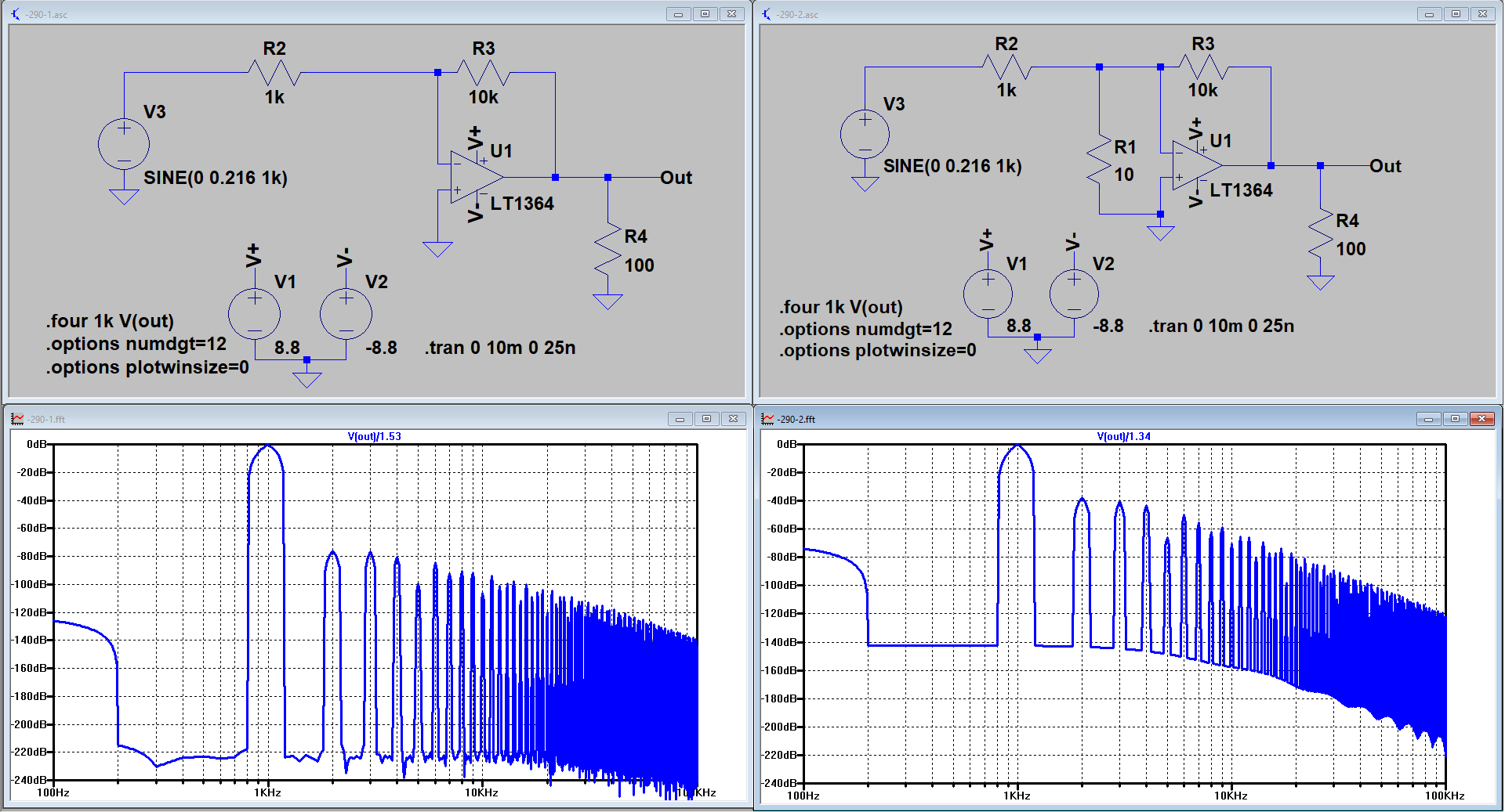
I started with the 4.32V p-p at the output that you mentioned, or 1.53Vrms. With the given circuit without the 10 Ohm resistor having a gain of 10, I had to apply 0.216V pk from the voltage source to get this 4.32V p-p.The results are divided by 8.87 and 10 respectively as shown at the top of the graph.
What is the reasoning?
However when inserting the 10 Ohm between the inputs, output voltage dropped from 1.53V to 1.34V rms, meaning that the gain dropped from 10 to 8.77, this because of the low open loop gain of the LT1364. Since I calculated the noise RTI (referred to the input) of the circuit, I had to divide both noise spectra resp. by 10 and by 8.77.
What I showed was not an FFT. I used the Noise function of LTSpice instead, as is visible in the images..noise V(out) V3 oct 50 20 20kAlso do you know how to remove the noise floor in the FTT? I could show some more useful figures if it wasn't in the way. I don't know how you made FTTs look like you showed before.
Hans
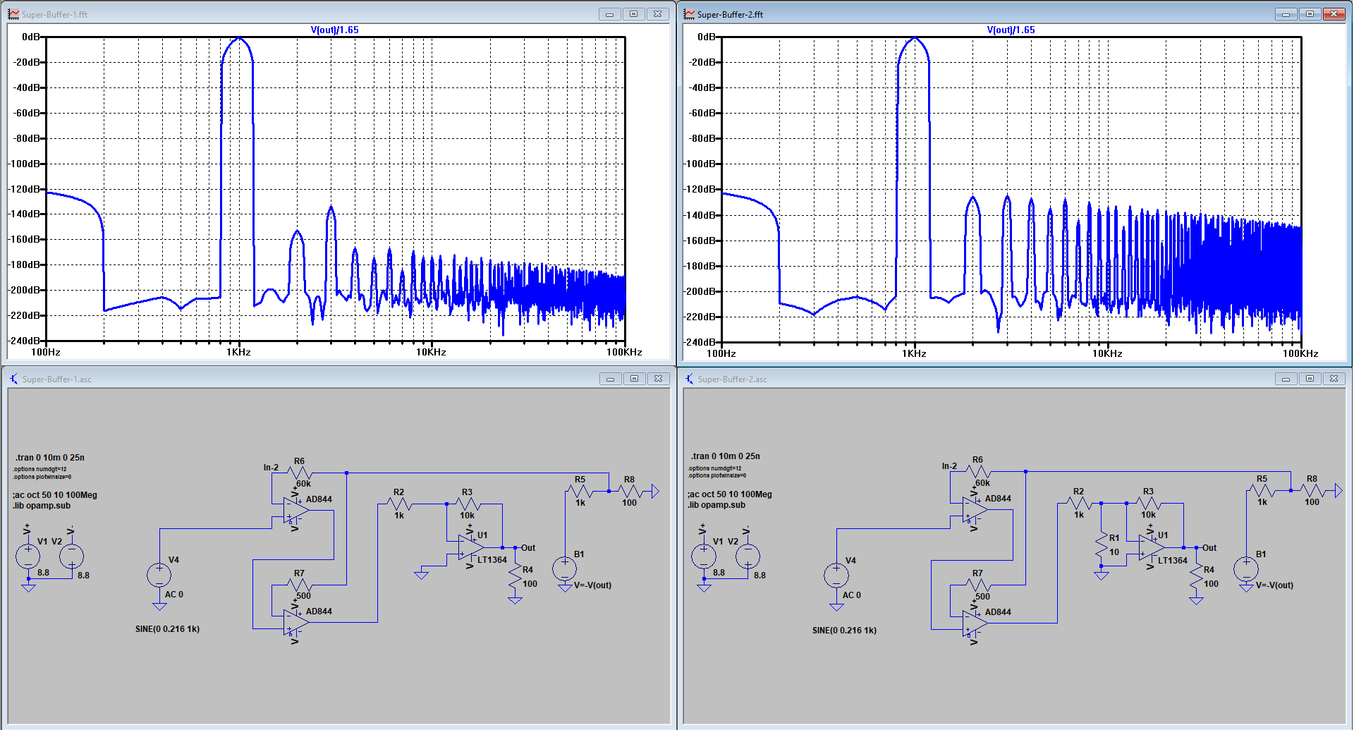
I see. You said you wanted the noise sim with my EC applied? I can only use half of the performance of my EC with the resistor method. However this would be the result with the usable half with no 10 ohm resistor

With the 10 ohm resistor

The output level was the same on both so I kept the division by 10.
The full scale circuit is not stable at a gain of 10 in the sim or in real life and the resistor causes it to go unstable even at unity. This is the result of the full scale circuit without the 10 ohm resistor at unity.

I think I was misconstruing what I was looking at because it was visually represented differently than mine. It looked like noise floor was removed with only harmonics. The harmonics on mine look like this

That was the result of the LT1364 by itself with no 10 ohm resistor under the same conditions you had it here. At least I think it is, it's a saved result from last night. The point is that my harmonics and noise floor are visually different.
The noise floor is annoying because like in real life the harmonics go into the noise floor after applying a decent amount of EC. I usually use transient analysis to see relative distortion in volts because of this.
With the 10 ohm resistor
The output level was the same on both so I kept the division by 10.
The full scale circuit is not stable at a gain of 10 in the sim or in real life and the resistor causes it to go unstable even at unity. This is the result of the full scale circuit without the 10 ohm resistor at unity.
Sorry I was referring to theseWhat I showed was not an FFT. I used the Noise function of LTSpice instead, as is visible in the images. .noise V(out) V3 oct 50 20 20k
Hans
I think I was misconstruing what I was looking at because it was visually represented differently than mine. It looked like noise floor was removed with only harmonics. The harmonics on mine look like this
That was the result of the LT1364 by itself with no 10 ohm resistor under the same conditions you had it here. At least I think it is, it's a saved result from last night. The point is that my harmonics and noise floor are visually different.
The noise floor is annoying because like in real life the harmonics go into the noise floor after applying a decent amount of EC. I usually use transient analysis to see relative distortion in volts because of this.
Last edited:
No, what is it?
Never mind, I thought I smelled a troll with an attitude.
Try
.option plotwinsize=0
.option numdgt=7
I think the difference you are seeing is just the floating point precision. Could be wrong.
Also check your maximum timestep.
.option plotwinsize=0
.option numdgt=7
I think the difference you are seeing is just the floating point precision. Could be wrong.
Also check your maximum timestep.
Last edited:
Yeah I use
.option plotwinsize=0
.option numdgt=7
I also like use at least 10n timestep because I usually measure in 20khz. Also or some reason my 1khz measurements look like this at the moment regardless of timestep which is annoying.

.option plotwinsize=0
.option numdgt=7
I also like use at least 10n timestep because I usually measure in 20khz. Also or some reason my 1khz measurements look like this at the moment regardless of timestep which is annoying.
@hellokitty,
I’ll have a closer look at your graphs as soon as I can find the time trying to understand the results and come back with my findings.
Regarding your FFT spectra, it seems that you have not used a window function where I have used the Hann window.
Hans
I’ll have a closer look at your graphs as soon as I can find the time trying to understand the results and come back with my findings.
Regarding your FFT spectra, it seems that you have not used a window function where I have used the Hann window.
Hans
Oh I didn't know it had window options.
Okay I changed it to Hann. I applied the EC to the LT1364 under the same conditions and increased the circuit sophistication in increments as far as I could go while keeping it stable at the 10X gain.
At 1X gain I could still squeeze more out of it.
I'm using 10khz instead of 1khz because I'm still getting that strange 1khz result.


The improvement in the last image is difficult to see but if you look carefully, the improvement of the main harmonics are consistent with the rest. Overall it is consistent with what I've seen in my tests and what I was expecting. I don't know what all the fuzz in the sim is though, doesn't appear when I'm simming without the window option.
But this is an example of why I assumed that the -290db value was correct getting the results I got. Every test and sim I've done suggests the improvements are independent of the state of the main amplifier.
Okay I changed it to Hann. I applied the EC to the LT1364 under the same conditions and increased the circuit sophistication in increments as far as I could go while keeping it stable at the 10X gain.
At 1X gain I could still squeeze more out of it.
I'm using 10khz instead of 1khz because I'm still getting that strange 1khz result.
The improvement in the last image is difficult to see but if you look carefully, the improvement of the main harmonics are consistent with the rest. Overall it is consistent with what I've seen in my tests and what I was expecting. I don't know what all the fuzz in the sim is though, doesn't appear when I'm simming without the window option.
But this is an example of why I assumed that the -290db value was correct getting the results I got. Every test and sim I've done suggests the improvements are independent of the state of the main amplifier.
Last edited:
I think that is flawed Marcel. The input of the opamp is not zero by definition - rather, it is, by definition, Vout/Aol. There must be some input to support the output. That means that the noise and non-linearity of that 10 ohms is also amplified, with the noise gain in this case.
Jan
Apparently you use a different definition for ideal op-amp than I do. To me, an ideal op-amp is basically just a silly nickname for a nullor, and a nullor by definition has zero input voltage and zero input current.
In any case, you can also use a perfectly linear voltage-controlled voltage source with a gain Aol, put a non-linear feedback network around it and then look at the trend for increasing Aol. It just complicates the thought experiment a bit.
In the case without the extra resistor, as long as the loop gain is large, the distortion will be nearly independent from Aol, because in this thought experiment, the distorting components are in the feedback network rather than in the controlled source.
Now add the extra resistor between the inputs of the controlled source, size it such that loop gain drops by a factor of 100 and again look at the effect of changing Aol. With increasing Aol, the voltage across the extra resistor decreases, so its impact on the behaviour of the circuit decreases. In fact, except for its thermal noise (*), you can make its impact as small as you like by increasing Aol further and further.
If the purpose of the extra resistor is to increase the distortion by a factor of 100, it clearly failed, because its impact tends to zero with increasing Aol, while the impact of the nonlinearity of the feedback resistors does not.
(*): If it has any; a hypothetical resistor might just as well be noise free.
Apparently you use a different definition for ideal op-amp than I do.
Ahh yes, I was assuming a real-world opamp. Sorry.
Jan
Never mind, I thought I smelled a troll with an attitude.
You might still be true. I often have these doubts with a poster that makes a generally intelligent impression but makes stupid (technically) and illogical statements. Benefit of the doubt in this case.
Jan
- Status
- Not open for further replies.
- Home
- Source & Line
- Analog Line Level
- -290 dB Distortion?