Zen V9 may measure better.... but does it sound better? 
Measurements vs. Sound Quality came to mind becasue i was thinking
of the Stereophile review of Yamamoto A-08 amp in this month's issue.
(It's a 2 Watt tube SET) Art Dudley gave it a good review - comparing it favorably
to his Lamm ML2.1s.
The funny thing was reading John Atkinson's measurement comments.
He said the amp was handsome and beautifully made.... LOL.
"Not much more than 300mW are available into 8 or 16 ohms at our
usual definition of clipping of 1% THD."
I'm building the Zen V8 now, and will probably build the Zen V9 too,
will be neat to listen to the differences in my system. 🙂
Ah, but...
Apassgear, what if you make a mirror of the circuit and run it parallel in order to achieve balanced/bridge mode?
I'm so curious!
John😀
Apassgear, what if you make a mirror of the circuit and run it parallel in order to achieve balanced/bridge mode?
I'm so curious!
John😀
Blues,
I think i remember reading that Mr. Pass said that as of right now
PassDIY wasn't going to be selling anything. I suppose it frees up
more time for Mr. Pass to crank out new Zen versions 🙂
I'm sure as long as we keep it not-for-profit, and for the members of
this Forum it wouldn't be a problem.
Of course there's nothing wrong with getting permission before proceeding.
point to point mania
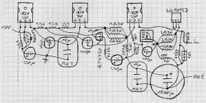
I have given it more thought and finnaly came upon the solution that will (hopefully) go into construction.
I think it offers small signal path lenghtht, em length (boy, my English is a bit blur today), actually it's designed to fit on one of them Eurocard/protoyping things.
I've checked a couple of times, but I don't guarantee that the design is free of wiring-mistakes.
The two ground-points should be connected "with a fat piece of wire" and then terminated to earth-ground via a resitor or one of them NTC things or else.
The pot will probably be a Bourns, cermet .5W.
Two remarks:
First, the power resitors should be mounted with a little distance from the PCB (maybe onto some individual stand offs where the big black dot are in the diagram) to allow some air to flow. There should also be some space to the right of the .47 3W Resistor.
The input resistor and the feedback network should be mounted at the bottom of the PCB. Else the power resistors will heat them up, which is bad if we want constant values. There will also be more space available on top of the PCB.
Second, the output-decoupling capacitors' placement is not ideal yet. As far as I know, bypass-capacitors should be placed closer to the load than the bypassed capacitor, which is true for the .47 3W resistor, but not for the 100 3W one. So there some improvement could be done. But maybe it doesn't matter dealing with such short distances. Your comment please.
Now some questions: How much power (VA) for the transformer? CLC-Filtering or will rectification and some big cans be enough? What happens if the value of the feedback-cap is increased?
Attachments
You can use a simple psu for this amp. The Capacitance multiplier clean up the supply rails really well. A couple of cans, say at least 30.000uF should do the trick.CLC-Filtering or will rectification and some big cans be enough?
A couple of 300VA trafos should be fine.
That P2P work look great.
Steen🙂
Yeap . . . really looks great . . .
As long as it is practical, I always go with p2p.
Personality . . .
More fun . . .
Flexibility . . .
Easier variation . . . (for this reason, I use a bit maginal lengths of wires . . . Noise pick up . . .? Errrrr . . . . . .)
But, do not do like the tooboo man, Choky, doing . . . teravle . . . 🙂
Regards
jh
As long as it is practical, I always go with p2p.
Personality . . .
More fun . . .
Flexibility . . .
Easier variation . . . (for this reason, I use a bit maginal lengths of wires . . . Noise pick up . . .? Errrrr . . .
. . .)But, do not do like the tooboo man, Choky, doing . . . teravle . . . 🙂
Regards
jh
moe29 said:I'm sure as long as we keep it not-for-profit, and for the members of
this Forum it wouldn't be a problem.
Of course there's nothing wrong with getting permission before proceeding.
Hi Moe,
I very much share your sentiment. The PCBs I am working on right now are really just because I wanted a few for myself, and for my buddy Steen as well as a few others. If I get a few made it will only be with Mr. Pass' permission and strictly NFP.
Cheers!
Russ
Russ White said:
Hi Moe,
I very much share your sentiment. The PCBs I am working on right now are really just because I wanted a few for myself, and for my buddy Steen as well as a few others. If I get a few made it will only be with Mr. Pass' permission and strictly NFP.
Cheers!
Russ
Russ,
I'm 😎 with your idea. Maybe I'd just want something from Mr. 😎 himself that I can afford (brand new) and as long as it's also 😎 with Mr. 😎 for you to proceed.
Thanks for your efforts.
Allan
I have a question, and, possibly, based on the answer a suggestion for Russ.
Would it work to implement ZV9 without the negative feedback (installment 3), but with the Aleph current source? Or does the Aleph current source require the feedback?
I do not know, at this point, whether I want a power transconductance amp or not and I would like to have the advantage of the Aleph current source regardless, if that's possible.
Assuming one can add the Aleph current source without the negative feedback, it might be nice if the PCB offered the ability to add it in or not.
Regardless, I would be interested in purchasing PCBs if and when they become available.
Thanks.
Paul Ebert
P.S. Russ, some time down the road, it would also be nice to have a balanced version to match the X-BOSOZ.
Yeah, I remember the day when the Pearl and ZenV4 boards and Q-packs was lying right there in my mailbox😎 That was great🙂Maybe I'd just want something from Mr. himself that I can afford (brand new)
That is nice reading😉 Lets hope that papa Pass will tell us what he is up to. I recall something like him saying that life is easy when not selling anything from PassDIY. More or less like Moe says. Lets see what happens🙂The PCBs I am working on right now are really just because I wanted a few for myself, and for my buddy Steen as well as a few others.
Steen🙂
Paul Ebert said:Russ, some time down the road, it would also be nice to have a balanced version to match the X-BOSOZ.
I fully agree on that point. 🙂 Since this circuit already shares an Aleph current source I wonder how far off base it is to consider a Super Symmetrical X-ZEN-V9. 😎
Hi,
Regarding post #90,
I was thinking about this as well...
Moreover... One idea is to mount a micro switch, which would turn on/off the Aleph current source, and the other micro switch that would connect/disconnect feedback resistors.
So, we would have four variations if I am not mistaken. But the question would be how to make these switches accessible from the outside, (long wires?) because it would not be fun to have to open a box every time we want to switch on/off the feedback, or the Aleph current source...
Any sugesstions?
regards
P.s. one could also incude a switch for the cascode el. capacitor...between ground/ or Source of Jfet...
Vix
Vix said:Hi,
Regarding post #90,
I was thinking about this as well...
Moreover... One idea is to mount a micro switch, which would turn on/off the Aleph current source, and the other micro switch that would connect/disconnect feedback resistors.
So, we would have four variations if I am not mistaken. But the question would be how to make these switches accessible from the outside, (long wires?) because it would not be fun to have to open a box every time we want to switch on/off the feedback, or the Aleph current source...
Any sugesstions?
regards
P.s. one could also incude a switch for the cascode el. capacitor...between ground/ or Source of Jfet...
Vix
little (takamisawa) relays?
Yes!
It would make ZEN a bit more complicated, but much more fun!
One could have a switch between transconcuctance/ordinary etc, modulated/normal cascode, Aleph/ Constant CCS....
with some twin color leds as indicators
Thanks,
Vix
It would make ZEN a bit more complicated, but much more fun!
One could have a switch between transconcuctance/ordinary etc, modulated/normal cascode, Aleph/ Constant CCS....
with some twin color leds as indicators
Thanks,
Vix
Re: Ah, but...
Balanced could work as long as both sides of the inductor have the same inductance and manage to have both sides of the circuit with same idle current plus all active devices to be thermally close connected.
Also, both amps from the balanced pair should share the same PSU.
carpenter said:Apassgear, what if you make a mirror of the circuit and run it parallel in order to achieve balanced/bridge mode?
I'm so curious!
John😀
Balanced could work as long as both sides of the inductor have the same inductance and manage to have both sides of the circuit with same idle current plus all active devices to be thermally close connected.
Also, both amps from the balanced pair should share the same PSU.
There are going to be a lot of BOSOZ preamps around now that Coulomb is shipping his parts kit (yeaaaaa!!!)
Then, as Russ points out a balanced SS XZ9 comes immedietly to mind!
Boy! the problem isn't coming up with ideas now that Nelson has done the breakthrough, its what to do first!! 😕
Then, as Russ points out a balanced SS XZ9 comes immedietly to mind!
Boy! the problem isn't coming up with ideas now that Nelson has done the breakthrough, its what to do first!! 😕
At 0,003% distortion, would one need an X-ed version?😀 The balanced input would be welcomed though🙂Then, as Russ points out a balanced SS XZ9 comes immedietly to mind!
Steen🙂
steenoe said:At 0,003% distortion, would one need an X-ed version?😀 The balanced input would be welcomed though🙂
Steen🙂
ooohhh.........
but why.........?
sorta over-engineering?
- Status
- Not open for further replies.
- Home
- Amplifiers
- Pass Labs
- Zv9