Susan,
the transformer is outside the domain of gate-source.
TonyTecson,
it would be disastrous for the prevailing idealism if distortion or operating bandwidth were measurable.
the transformer is outside the domain of gate-source.
TonyTecson,
it would be disastrous for the prevailing idealism if distortion or operating bandwidth were measurable.
@ N101N,
I have the following suggestion for you:
Read this thread and try to understand the design.
If you have something constructive to contribute, please do so.
If not, which is the case until now, please go.
I have the following suggestion for you:
Read this thread and try to understand the design.
If you have something constructive to contribute, please do so.
If not, which is the case until now, please go.
Testing...
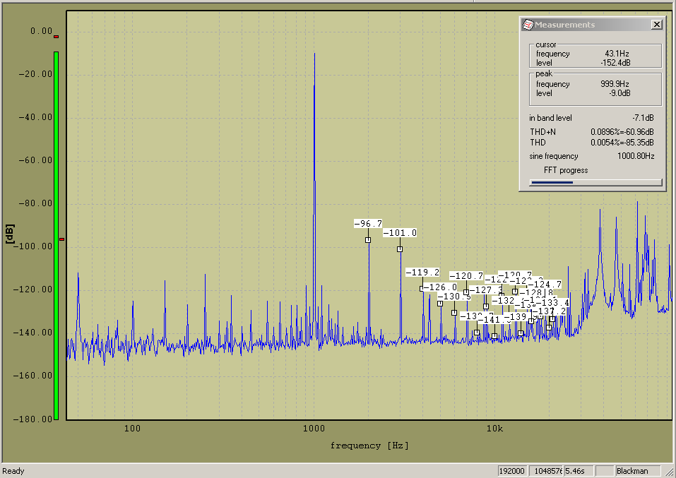
From my very much in need of an update webpage... Zeus MOSFET SE Preamp & PP Power Amp System THD Test - November 2005
1.1 watts = 2.89 volts into 8 ohms - 1 kHz FFT (-9dB) - 0.0054% THD
The stuff above 20KHz is from the computer switched-mode power-supply, which I leave in to fully show the testing method.
Last edited:
As an aside I would note that my current stereo setup (as per the schematic in post #1683) has been in daily use for something like 14 years.
So therefore the power-supplies have been on for about 120,000 hours (they go into standby when the pre is turned off but the electronics is still running), and the pre and power amps have been on for about 50,000 of those hours.
So therefore the power-supplies have been on for about 120,000 hours (they go into standby when the pre is turned off but the electronics is still running), and the pre and power amps have been on for about 50,000 of those hours.
Hi, Susan, i have been using smps psu on my amp builds, i am toying with the idea of chokes, but have not yet gone into it...a ferrite choke external to the smps to filter out hf astifacts...
Last edited:
As an aside I would note that my current stereo setup (as per the schematic in post #1683) has been in daily use for something like 14 years.
So therefore the power-supplies have been on for about 120,000 hours (they go into standby when the pre is turned off but the electronics is still running), and the pre and power amps have been on for about 50,000 of those hours.
Hello Susan
what caps you're using in the PSU that they resist for such a long time; are they still holding the capacitance like new?
Hi, Susan, i have been using smps psu on my amp builds, i am toying with the idea of chokes, but have not yet gone into it...a ferrite choke external to the smps to filter out hf artefacts...
Hi Tony,
I made up a dual stage LC filter for a 48V SMPS which did the job.
As the switching frequency is high compared to the mains it is much easier to smooth things out and one can hand wind one's own chokes to optimise them.
However, there can still be near-field pickup from the PSU itself which makes sorting out what is real and what happens to be seen by the scope to be "interesting".
I am using an external +24V brick type psu for one of my preamps, the one that drives the centre speaker in our 5.1 setup which is SE. Seems to be working fine.
Hello Susan
what caps you're using in the PSU that they resist for such a long time; are they still holding the capacitance like new?
Hi Joao,
I use industrial rated electrolytic capacitors, with the best working lifetime I can afford.
When the power-supply is in standby, the main electrolytic is not powered; just a small capacitor to keep a DC voltage after the rectifier.
The power into the electrolytic is current limited to a maximum of 10A peak and half that for turn-on, so there is not the normal turn-on surge which is the main thing that gets the bigger old electrolytics. The cap takes a second or two to power up to full rail.
The power-supply circuit is more complicated than the amplifier itself.
Attachments
Transformer coupled Sub-Bass...
This is a very short movie clip of my transformer coupled Sub-Bass speaker in action, it really is running this slowly it is not a video-effects speed-change.
The Driver is a Vibe SPACE 15D4, 15 inch (ca. 38 cm) 3600 Watt Subwoofer.
This is a very short movie clip of my transformer coupled Sub-Bass speaker in action, it really is running this slowly it is not a video-effects speed-change.
The Driver is a Vibe SPACE 15D4, 15 inch (ca. 38 cm) 3600 Watt Subwoofer.
Attachments
Hi Tony,
I made up a dual stage LC filter for a 48V SMPS which did the job.
As the switching frequency is high compared to the mains it is much easier to smooth things out and one can hand wind one's own chokes to optimise them.
However, there can still be near-field pickup from the PSU itself which makes sorting out what is real and what happens to be seen by the scope to be "interesting".
I am using an external +24V brick type psu for one of my preamps, the one that drives the centre speaker in our 5.1 setup which is SE. Seems to be working fine.
thank you....
Hi Joao,
I use industrial rated electrolytic capacitors, with the best working lifetime I can afford.
When the power-supply is in standby, the main electrolytic is not powered; just a small capacitor to keep a DC voltage after the rectifier.
The power into the electrolytic is current limited to a maximum of 10A peak and half that for turn-on, so there is not the normal turn-on surge which is the main thing that gets the bigger old electrolytics. The cap takes a second or two to power up to full rail.
The power-supply circuit is more complicated than the amplifier itself.
That's what I expected 🙂 Looking / comparing the datasheets from the "audio grade" caps with industrial grade could be astonishing for many diy builders (lifetime, temperature, ripple current etc.)
Can you explain the sonic benefits of your circuit to normal follower circuits (tube, solid state).... my experience on the common circuits are sonical not the my "cup of tea" but maybe your findings look interesting to me.
Someone has STW34NB20?
Or Other Susan suggested for the project?
Matched would be better.
Thanks
V
Or Other Susan suggested for the project?
Matched would be better.
Thanks
V
After a lot of time spent looking for 'unobtaineum' - and any pspice models for them - I found what appears to be an upgraded IRFP250
Available from RS Components - one of the cheapest of this series
IRFP250MPBF - RDS on 0.075 ohm, Crss 83p , 17 S , Vth 3v
STW34NB20 - RDS on 0.075 ohm, Crss 90p , 17 S , Vth 4v
vs
IRFP250 - RDS on 0.085 ohm , Crss 240p, 12 S
Which is what I'm going to roll with . Somewhere in this long thread is a discussion of the improvement in THD due to the lower Crss of the STW34NB20 , and given the lower Vth and low cost , I'm going to roll with this one .
Hope this helps someone ..
PG
Awesome; the IRFP250MPBF do indeed look like a good match 🙂
Thanks for the post, appreciated.
Thanks for the post, appreciated.
Admitted. Good amp, smart supply. A good reference!The power-supply circuit is more complicated than the amplifier itself.
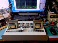
My tube/bipolar hybrid line-driver is finished!!!
The 19” 2U front-panel for my tube/bipolar hybrid line-driver has finally come back into stock with Farnell, so I have finally been able to finish this preamp project.
I also made some feet (white ABS).
Using my HP8903B with a 1kHz test tone, THD is 0.018% with a 500mV input and 1.2V output into 600 ohms.
( For comparison the HP8903B loopback distortion measures 0.0044% )
FFT shows input at -10db, and 3rd harmonic at -90db.
Total current at a nominal 24 volts is 0.68 amps.
N.B. I made a nice little DC/DC converter to give a 120 to 200 volt anode supply for the tubes, but that proved not to be needed as the 7N7 vacuum-tubes are running with the 24 volt supply for their anode B+ volts.
Attachments
-
 susan-hybrid-triode-bipolar-line-driver-on-workbench-2-DeNoiseAI-denoise_DxO.jpg164.1 KB · Views: 559
 -
 susan-hybrid-triode-bipolar-line-driver-on-workbench-1-DeNoiseAI-denoise_DxO.jpg148.6 KB · Views: 542
 -
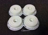 susan-pre-amp-3d-printed-feex4-1-DeNoiseAI-denoise_DxO.jpg177.9 KB · Views: 546
 -
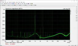 201128-hybrid-pre-ffts-distortion-HP8903B-source-500mV-1khz-left-10db1st-90db3rd-THD=0_018pc-600.png38.5 KB · Views: 511
Last edited:

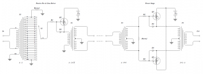
Just to avoid sweeping through 1700 posts, but what's the final circuit look like? Curiosity.
Schematics PNG and PDF
Hi MarsBravo,
The current schematic in PNG and a PDF version with suggested transformer sets.
The hybrid line-driver replaces the DMOS MOSFET with a triode/bipolar follower.
In the current prototype as just posted the line-driver (left side of schematic) is push-pull not single-ended.
Hi MarsBravo,
The current schematic in PNG and a PDF version with suggested transformer sets.
The hybrid line-driver replaces the DMOS MOSFET with a triode/bipolar follower.
In the current prototype as just posted the line-driver (left side of schematic) is push-pull not single-ended.
Attachments
Last edited:
- Home
- Amplifiers
- Solid State
- Zero Feedback Impedance Amplifiers