Me too, the Pearl 3 and the F6m that 6L6 has mentioned above would be great projects - just like all the Pass designs!!

checking startup is for Sissies
we, brave builders, we are just flippin' damn power switch!!

Real brave builders do not need a stinkin' power switch.
We just need a vacuum cleaner....
Pa: "Where tf is ZM??"
6L6: "Here, he's transforming!!"

6L6: "Here, he's transforming!!"
Not himself, only ZMs curled hair, that is enough for a good amp!
:--)
:--)
Zenductor-Pearl3-F6m this year joy ,tnxMe too, the Pearl 3 and the F6m that 6L6 has mentioned above would be great projects - just like all the Pass designs!!
Attachments
And F5m as well.
I think the F5m will be the star of the show - 2.5" x 3.5" board!
Since this thread has opened additional topics, I have some thoughts on a revised F6.
The most up to date questions and building tips on the F6 may be found here: https://www.diyaudio.com/community/threads/f6-illustrated-build-guide
While it is possible that some builders may have wished for the possibility of alternate signal transformers, that topic has not arisen (at least in the last couple years) on this thread. There are other discussions regarding the biasing networks and output source resistor loading, either or both of which could easily be addressed with a new PCB design.
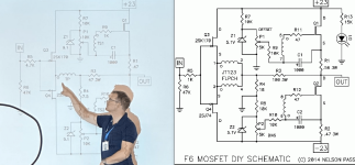
My recommendations would include a simple provision for substituting a string of three small LEDs in place of the zener diode. The green LiteOn LTL-4231N LEDs in particular provide superior voltage regulation with a negative temperature coefficient. It would be very straightforward to implement combined component footprints on the PCB that would allow for either zener diods or LEDs to be used, depending on the preference of the builder. Many of us have already stacked three series LEDs into the existing spot designated fort the Zener diode.
The next recommendation is to include provision for an alternate source resistor network below Q1. I have found a preferred sound may be achieved by using 0.05 Ohms above the coupling capacitor node and 0.40 Ohms below that node. My preference is for 15W 1% Bourns thick film resistors instead of the moire typical 3W 5% axial resistors. This provision allows the harmonic profile of the output stage to be better tuned to the listener's preferences. This provision is only required for the network below Q1.
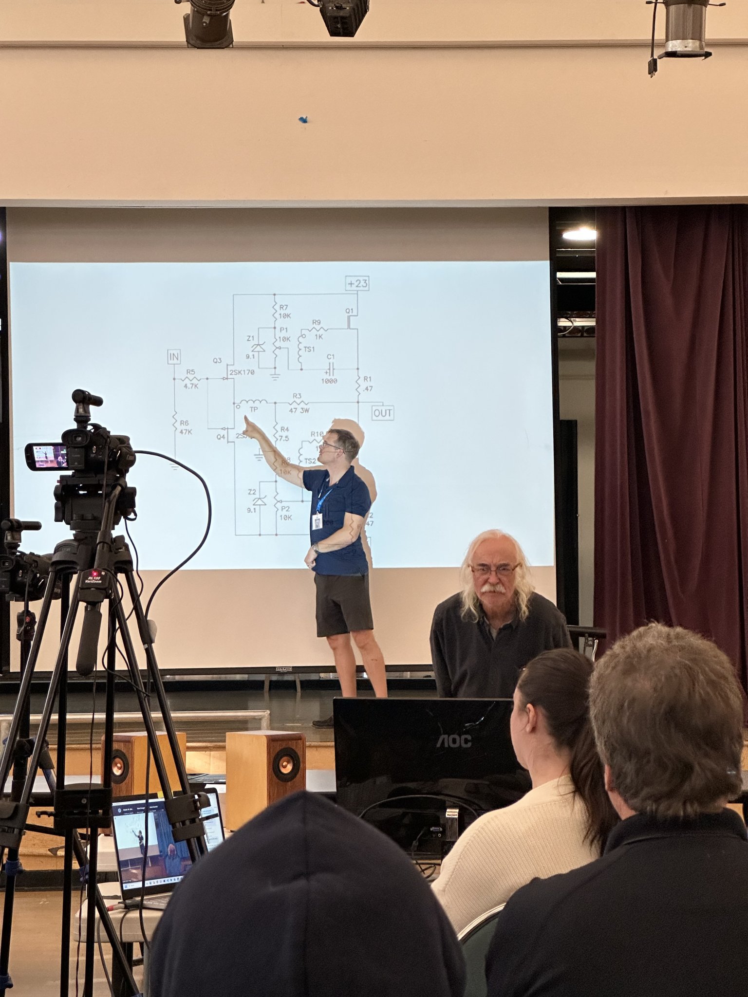
The F6 is a very capable amplifier that employs a remarkably simple component topology. It may be built as an extraordinary amp with careful selection of that limited number of components. My preferred output Mosfets are the FQH44N10, but the IRFP048 devices may be used to nearly the same effect. In either case, bias currents from 1.6 to 1.8 Amps may be found to give the best sound. Such bias currents really need the negative tempco voltage regulation in their bias networks to let the amp reach thermal equilibrium in a reasonable amount of time.
Once the output devices (and even the input buffer) have become optimized the Jensen signal transformer becomes the final component which defines the sound of the F6. While others may have different ideas, I would not advocate going for a cheap solution here. The JT123 FLPCH is specially made to be used in the most demanding small signal amplification applications. It is a little more expensive for a very good reason.
The most up to date questions and building tips on the F6 may be found here: https://www.diyaudio.com/community/threads/f6-illustrated-build-guide
While it is possible that some builders may have wished for the possibility of alternate signal transformers, that topic has not arisen (at least in the last couple years) on this thread. There are other discussions regarding the biasing networks and output source resistor loading, either or both of which could easily be addressed with a new PCB design.
My recommendations would include a simple provision for substituting a string of three small LEDs in place of the zener diode. The green LiteOn LTL-4231N LEDs in particular provide superior voltage regulation with a negative temperature coefficient. It would be very straightforward to implement combined component footprints on the PCB that would allow for either zener diods or LEDs to be used, depending on the preference of the builder. Many of us have already stacked three series LEDs into the existing spot designated fort the Zener diode.
The next recommendation is to include provision for an alternate source resistor network below Q1. I have found a preferred sound may be achieved by using 0.05 Ohms above the coupling capacitor node and 0.40 Ohms below that node. My preference is for 15W 1% Bourns thick film resistors instead of the moire typical 3W 5% axial resistors. This provision allows the harmonic profile of the output stage to be better tuned to the listener's preferences. This provision is only required for the network below Q1.
The F6 is a very capable amplifier that employs a remarkably simple component topology. It may be built as an extraordinary amp with careful selection of that limited number of components. My preferred output Mosfets are the FQH44N10, but the IRFP048 devices may be used to nearly the same effect. In either case, bias currents from 1.6 to 1.8 Amps may be found to give the best sound. Such bias currents really need the negative tempco voltage regulation in their bias networks to let the amp reach thermal equilibrium in a reasonable amount of time.
Once the output devices (and even the input buffer) have become optimized the Jensen signal transformer becomes the final component which defines the sound of the F6. While others may have different ideas, I would not advocate going for a cheap solution here. The JT123 FLPCH is specially made to be used in the most demanding small signal amplification applications. It is a little more expensive for a very good reason.
You should make a PCB with those changes. Seriously. It works and plenty of people have tried/tested it. Include pads for whichever transformer you deem best, or multiple pads.
The FQH44N10 seems like an obsolete part, other recommendations or should we stick with IRFP048 ?
Thanks
Eric
Thanks
Eric
I can’t promise anything in the near term for designing a new F6 PCB. Learning KiCAD keeps getting moved to the back burner to accommodate other amp building projects. If I do manage to pick up KiCAD, my F6 would sport a diamond buffer as its input stage in addition to the other mods mentioned.
Yes, the FQH44N10 is no longer in production. I have a tube of NOS parts from Fairchild, but that was a lucky find. The combination of high transconductance, low input capacitance and low total Gate charge is difficult to find. The IRFP048 is better than the IRFP240 in these parameters, so it’s a viable choice.
Yes, the FQH44N10 is no longer in production. I have a tube of NOS parts from Fairchild, but that was a lucky find. The combination of high transconductance, low input capacitance and low total Gate charge is difficult to find. The IRFP048 is better than the IRFP240 in these parameters, so it’s a viable choice.
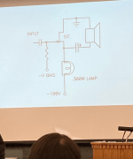
Minimalist, according to Nelson.
I thought it was mucho cheap?
If you draw the complete schematic on paper, paint or something, I may have time to draw a PCB for it.I can’t promise anything in the near term for designing a new F6 PCB. Learning KiCAD keeps getting moved to the back burner to accommodate other amp building projects. If I do manage to pick up KiCAD, my F6 would sport a diamond buffer as its input stage in addition to the other mods mentioned.
Yes, the FQH44N10 is no longer in production. I have a tube of NOS parts from Fairchild, but that was a lucky find. The combination of high transconductance, low input capacitance and low total Gate charge is difficult to find. The IRFP048 is better than the IRFP240 in these parameters, so it’s a viable choice.
and a little more ....And F5m as well.
😎
Attachments
- Home
- Amplifiers
- Pass Labs
- Zenductor