You speak my language sir. All that stuff sounds exciting!This schematic is the F6m, which is a tweak to the F6 that uses a different transformer than the original, which is more readily available and more inexpensive. Nice!
SITLight
Brings back memories
My first NP amp
I had an amp like that, once, I think... next to my lava lamps.
But then in California they pushed LED bulbs....
I think I broke the amp and the lava lamps. 😛
My Zenductor is up and sounds really nice right away. At 0.5 V across R1, the heatsinks settled at 75 deg C (!). Ambient temp is 21 deg C. Listening with zero feedback for now. It’s fun to change the feedback on the fly.
I turned up my sub a bit, as the bass is less than the M2X.
Current setup:
Roon NUC —> Schiit Bifrost DAC —> Mark Johnson’s Noir HPA —> Zenductor —> Zu Druid V + Undertone sub

I turned up my sub a bit, as the bass is less than the M2X.
Current setup:
Roon NUC —> Schiit Bifrost DAC —> Mark Johnson’s Noir HPA —> Zenductor —> Zu Druid V + Undertone sub

Very nice.. Those Zu Druids are probably some of the few full range speakers that are efficient enough to work well with lower powered amps.
There is work in progress.. Mikerodrig27 has graciously been drawing a new F6 PCB with all the features, including a Diamond buffer input stage. Stay tuned.You should make a PCB with those changes. Seriously. It works and plenty of people have tried/tested it. Include pads for whichever transformer you deem best, or multiple pads.

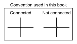
By the way, I'm an old guy, I like the old style. You can not believe how much time and pain and suffering I spent because the schematic uses the newer convention for not connected:

To my eye, the choke was wired across the load.... and I could not, for the life of me understand what that circuit was doing.
Thanks Jim for pointing out that the trace is NOT connected.
I suppose I should not try to understand what a design does at 2AM when my mind is stuck at Electro-Bowl with a guy named Carl in his Bob Square Pants pajamas...
https://www.diyaudio.com/community/threads/build-this-mofo.313649/
Attachments
Last edited:
To my eye, the choke was wired across the load
how's that?
which schm exactly you're looking at?
anyhow, choke must be connected from upper rail to drain of mosfet
one end of load must be connected to drain (cap or not)
other end of load can be connected either to GND or upper rail (not or cap)
just imagine circuit printed on paper and laid on top of table
then start walking around the table, staring at circuit
in short time everything is going to be either much clearer ........ or totally unclear

but, in long term, very useful routine

... The green LiteOn LTL-4231N LEDs in particular provide superior voltage regulation with a negative temperature coefficient. ...
... The next recommendation is to include provision for an alternate source resistor network below Q1. ...
These are the two points were I disagree:
- "superior voltage regulation" actually implies a temperature coefficient as low as possible. In revision 2 of the F6 schematic, Nelson uses a TL431. (I used a LM329 for the same effect). Besides that green LEDs are ugly. ;-)
- "alternate source resistor" again this is already addressed by Nelson with a better solution, P3 which lets you exactly adjust the harmonic profile like in the factory made version.
The F6 schematic R2:
https://www.diyaudio.com/community/attachments/f6_sch_r2-jpg.1187477/
With well thought out solutions from Nelson Pass I don´t see the point for "modding".
Isn’t “modding” a big part of why this forum exists?

Modding is definitely where it's at 😉
It is good to see additional work on the F6. Rev 2 has some nice provisions.
In the context of taking the F6 beyond the original First Watt envelope, the biasing networks needed to be revisited to address issues that that are inherent to higher bias / power Class A amplifiers. That is the time required to reach thermal equilibrium, and avoid the potential for thermal runaway. Due to these issues it is necessary to have bias networks with a small negative temperature coefficient. Near-zero (slightly positive) coefficients such as exhibited by the TL-431 or LM329 work in other applications, but are not the best solution for an amp that is intended to run hot.
My initial build of the F6 used LM329 voltage sources in place of the Zener diodes. It also was running from +/– 26.5V power rails with 1.8A of bias current through my preferred Mosfets. It needed at least 1.5 hours before it would settle in to stable current and output offset measurements. I got in the habit of leaving it alone for 2 hours just to be sure. After switching to the green LED strings, the same amp settles down around 45 minutes, and doesn't deviate significantly from that mark after an hour. There is actually a separate thread on this topic, started by 2 picoDumbs. Many builders have found that thread to be very instructive. The short story is that a negative temperature coefficient initially sets a higher Gate voltage at the output devices, then automagically backs that voltage down as the amp heats up. Very handy.
how's that?
which schm exactly you're looking at?
anyhow, choke must be connected from upper rail to drain of mosfet
one end of load must be connected to drain (cap or not)
other end of load can be connected either to GND or upper rail (not or cap)
just imagine circuit printed on paper and laid on top of table
then start walking around the table, staring at circuit
in short time everything is going to be either much clearer ........ or totally unclear
but, in long term, very useful routine
See post #269 above..
Anyhow, I completely agree with you.
In the schematics, the trace going across the choke crosses another line.... when I was looking at it, I thought it was connected, it was sort of late at night.
Once I saw it that way, I could not unsee it.
At BA23, Jim pointed out it was NOT connected... Duh!
BTW, interesting idea of walking "around" the circuit. I usually go from left (input) to right (output). Sometimes, I may go right to left. Perhaps, as you noted, I should pay more attention to the flow from the Vcc+ to Vcc- and GND.
I guess another idea is to look at the flow of power as being set in a statis (bias in output) and regulated by the input (FE).
Last edited:
Thank you Mike and Nelson for sharing this design. Thank you Jim for patiently helping me complete this on the day.
Does anyone have recommendations for an enclosure? It fits nicely in a tin lunch box but I am not sure that is ideal.
—Nandu
Does anyone have recommendations for an enclosure? It fits nicely in a tin lunch box but I am not sure that is ideal.
—Nandu
I am working on a 3D printed base to move the terminating connections. If it works well, I will share it here.
Are these going to be available in the store? Probably asked and answered already, but I am too lazy to go wading.
- Home
- Amplifiers
- Pass Labs
- Zenductor