Post. #159
I was thinking of putting them side by side on a common Hammond Tube Chassis. Hiding the power bricks below.
If I went with a 10x7x3 it would fit nicely and I could fit them in one chassis with one shared AC plug...
OTOH, if I went with twin 10x5x3 I could put them close to the speakers with short cables. ( I got long enough line level cables..).
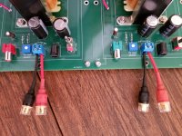
BTW, I got these five way pigtails to fit in my vintage audio units... but they fit perfectly here:
https://www.amazon.com/gp/product/B07W7MPHWB/ref=ppx_yo_dt_b_search_asin_title?ie=UTF8&psc=1
I was thinking of putting them side by side on a common Hammond Tube Chassis. Hiding the power bricks below.
If I went with a 10x7x3 it would fit nicely and I could fit them in one chassis with one shared AC plug...
OTOH, if I went with twin 10x5x3 I could put them close to the speakers with short cables. ( I got long enough line level cables..).
BTW, I got these five way pigtails to fit in my vintage audio units... but they fit perfectly here:
https://www.amazon.com/gp/product/B07W7MPHWB/ref=ppx_yo_dt_b_search_asin_title?ie=UTF8&psc=1
Attachments

The schematic is available and published. Everyone can feel free to lay out their own personal PCB implementation, including allowances for different / better / more expensive / trendy avant garde components. Don't like the rectangular shape? Change it!! Want an EMI shielding ground plane and a 4 layer board? Make it!! Want different I/O connectors? Install those PCB footprints. Prefer XLR balanced input? Circuit design an appropriate implementation and plop it in.
After you build it and verify that it works well, you can upload your design here and let other DIYers try a Zenductor modified exactly your way.
After you build it and verify that it works well, you can upload your design here and let other DIYers try a Zenductor modified exactly your way.
After you build it and verify that it works well, you can upload your design here and let other DIYers try a Zenductor modified exactly your way.
Love it! DIY forever!!

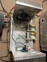
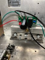
Exactly!! just whipped these up, should be here shortly. Went with 6800uF for the output cap, and a 0.50R/100W source resistor (ease of mounting). I use a 1"X1" alu bar with a single bolt hole for mounting, gets the fet and resistor in one shot. Looking for 24V (smps) and about 2.5A with a 193V inductor, I think the sinks will keep it alive. Pics attached are an FAOW running at 24V/2A I've been dailying, keeps it cool. Thanks again NP/Mike/Jim! I'd be happy to share gerbers, once I verify it doesn't blow up.
John
John
Attachments
Last edited:
I can't quite find the Triad inductors in those photos (post #288); are they out-of-frame, connected by flywires?
The photographs are of the FAOW, I believe.
https://www.diyaudio.com/community/threads/faow.325037/
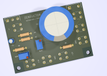
The render of the proposed board for the Zenductor on the far right shows pads for the inductor in the upper left, if I've understood correctly. So they'd be connected with flywires, I believe. I think the boards are on the way, and the Zenductor hasn't yet been built in this configuration.
Lots of "I think", and "I believe"...
John, am I close?
https://www.diyaudio.com/community/threads/faow.325037/
The render of the proposed board for the Zenductor on the far right shows pads for the inductor in the upper left, if I've understood correctly. So they'd be connected with flywires, I believe. I think the boards are on the way, and the Zenductor hasn't yet been built in this configuration.
Lots of "I think", and "I believe"...
John, am I close?

I like the idea of exploring alternate chokes and power supplies.
Especially for those of us who have parts left over from other experiments (ex: MoFo). Specifically, I would probably try the 24V MeanWell PSU originally used for the ACA, together with some MOT transformers @ 70mH and 0.5Ω DC.
Especially for those of us who have parts left over from other experiments (ex: MoFo). Specifically, I would probably try the 24V MeanWell PSU originally used for the ACA, together with some MOT transformers @ 70mH and 0.5Ω DC.
exactly. Was just showing an alternate way to mount it (or how I do it), makes testing various designs easy. Yes, a 100W source res is beyond overkill, but it aids in mounting and its non-inductive....so I got that going for me, which is nice.The photographs are of the FAOW, I believe.
https://www.diyaudio.com/community/threads/faow.325037/
The render of the proposed board for the Zenductor on the far right shows pads for the inductor in the upper left, if I've understood correctly. So they'd be connected with flywires, I believe. I think the boards are on the way, and the Zenductor hasn't yet been built in this configuration.
Lots of "I think", and "I believe"...
John, am I close?
^ It was a Cinderella story, but you're the belle of the ball.
Edited to add - Big hitter, Papa... (Couldn't resist).
Edited to add - Big hitter, Papa... (Couldn't resist).
I finally got around to powering up the Zenductors at home. Let them burn (figuratively) for three hours. After about two hours they settled to a nice and very steady 500mV. The house is hot ( trying not to run the AC) so it's about 80F inside. The heat sinks were at 78C. I set it up so the gain was about a quarter of the way up.
Plugged in the same set up I lent for a while last Saturday... my phone and portable DAC... playing Tidal HiFi... at first I had the Elac BS41-BK (sort of sacrificial), afterwards I brought out the Unifi-2 UB52.
First off, this is not a giant killer amp... not with anything under 87db/w at least. However, they have no right to sound as good as they do.
Even with the El Cheapo speakers, voices sounded clear, the treble was extended and the bass had speed to it. It didn't play loud and the dynamics were so so.. after a while I figured it was time to upgrade the speakers in the test rig.
Wow!
The dynamics got much better, the presentation was cleaner. I'd say that overall the presentation was a bit up forward but in a very good way. Vocal harmonies were quite good and I could follow the individual voices.
I suppose to get the best feel for these amp I ought to replace the SissySIT in the main rig with them and see.... maybe next week.
In any event, now to get a base and likely a clear case dust cover for them.
To tell you the truth.. if I didn't have a house full of stuff, I could live with these amps, the Elacs Unifi2 UB52, the Topping NX4 DAC and Tidal HiFi. It won't play loud but it will play quite nice. If you remember, I set that front end for a couple of hours in the build room at BA23.... remember I was playing Cecilio and Kapono and later Cream? Even those Radio Shack Minimus 7 were playing very nicely.
Heck, at one point I was playing Fortunate Son by CCR and wife came up and started dancing to it... THAT's what it's all about! HAPPY wife HAPPY home...
Ynomofo2? Variant
This may be the silliest post of late but I'll bear the embarrassment.
Might this work with the new V- set to match the dc voltage drop across the added lower inductor? The result, in my imagination is a differential output, big swing on top, smaller on the bottom, but inverse phase symmetrical. Might not be worth the effort. I just like the "Super-SymmetriDuction" feature name.
Thanks to you both!, the notion that the inductors would cancel the current between them was nagging me, but I couldn't see my way clear there. And, of course, putting the circuit into LT Spice would have pointed that out almost instantly. I've resisted getting more deeply involved in one area or another, concentrating on system building. I'm also cautious about specific rabbit holes given my age. Nonetheless, every once and a while, I find some concept compelling.
As I stared at the posted modified shematic, I also noticed that the P1 negative end would have to go to the V- below the lower inductor. I'm sure there are other issues in this already remarkably quiet design.
Thanks again.
As I stared at the posted modified shematic, I also noticed that the P1 negative end would have to go to the V- below the lower inductor. I'm sure there are other issues in this already remarkably quiet design.
Thanks again.
- Home
- Amplifiers
- Pass Labs
- Zenductor