No I meant a class-B (or even AB). How critical is the exact bias setting?
I would think deviations from the optimal setting of say 5% would not be audible? In one of my tests I changed the bias of a class AB amp from +5% of optimum to -5% of optimum and could hardly see any change in the distortion residual, although the THD value did move a few digits on the far right.
Jan
Well, I had to look that one up, on p507 of APAD6, to be precise. If the criterion is a visible change in the residual:
An EF stage needs to be within +/- 4%
A CFP stage needs to be within +/- 2%
This is obviously approximate because of the difficulty of defining "visible change" in the residual, but you are certainly in the right ballpark for the EF stage. The CFP stage is more critical because of the much smaller Vq (quiescent voltage across the output emitter resistors) which is only partly offset by the fact that the bias voltage is half as big as for the EF case.
This only relates to Class-B, of course. If you overbias into Class-AB there is no optimal bias setting, you just get a bigger Class-A region around 0V as the bias is increased.
Last edited:
The CFP stage is more critical because of the much smaller Vq
The CFP stage is quite questionable, due to its narrow and sharp transition crossover area. It produces more high harmonics (compared to 2EF), which is all but desirable. It is also more prone to local oscillations.
Yes Pavel, see attached, from the upcoming (first!) Linear Audio book:
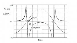
Power device current of emitter follower, Bryston and CFP output stage low-frequency crossover. Output voltage dashed. Transistor currents zoomed to show crossover region. Solid = Bryston, dotted = emitter follower and solid grey= CFP.
CFP is very sharp, leading to a spray of higher order harmonics.
Jan
Attachments
I am planning to build a CFP output stage and your comments are really frightening.
Can this sharpness be mitigated ?
Can this sharpness be mitigated ?
Yes Pavel, see attached, from the upcoming (first!) Linear Audio book:
Power device current of emitter follower, Bryston and CFP output stage low-frequency crossover. Output voltage dashed. Transistor currents zoomed to show crossover region. Solid = Bryston, dotted = emitter follower and solid grey= CFP.
CFP is very sharp, leading to a spray of higher order harmonics.
Jan
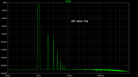
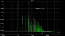
Hi Jan, please let me show FFT view to the same problem. We can see it very clearly at low signal level. Attached are spectra for 2EF and CFP output stages, loaded with 4 ohm, at 1Vp output voltage. Re is 0.1 ohm in both cases. V(Re) is 23mV for 2EF and 3.2mV for CFP, values close to 'optimal' according to D. Self book.
Attachments
I am planning to build a CFP output stage and your comments are really frightening.
Can this sharpness be mitigated ?
Only in case you would build class A CFP. CFP seems appealing for class B (AB), as it requires lower bias current (= less power) for 'optimal' THD. For output amplitudes like 10V, yes, overall THD is lower than for 2EF. Spread of harmonics remains always almost to infinity, but they are seemingly lower in amplitude for higher output voltages. But, for lower amplitudes about 1V (which is the level where you normally listen at room level for most time), high harmonics for 2EF output stage almost disappear, though for CFP they become dominant. Then you have only a NFB to suppress them. IMO, and I am pretty convinced about it, this is the reason of 'sterile' sound of amplifiers with class B CFP output. I use the term 'class B' for 'optimally biased' AB according to D. Self.
I am planning to build a CFP output stage and your comments are really frightening.
Can this sharpness be mitigated ?
Agree with PMA. CFP's are great when in class A, so use them as (pre)drivers in class A! That will really help the amp linearity.
The reason for the 'sharpness' is the very high internal feedback. The feedback linearises the circuit up to the very last milivolt, but when it runs out of loop gain, it really crashes.
Similarly with a feedback amplifier that is clipping: the distortion remains very low until the last millivolt, but when it runs out of loop gain you're really in trouble.
That's why soft clippers are such a good idea to improve amplifier sound even if the measurements get a bit worse.
jan
Thank you gentlemen.
Maybe that is why my first CFP output build needs such high bias to sound good at low level listening. (It is in reality working in class A)
Maybe that is why my first CFP output build needs such high bias to sound good at low level listening. (It is in reality working in class A)
Yes Pavel, see attached, from the upcoming (first!) Linear Audio book:
Power device current of emitter follower, Bryston and CFP output stage low-frequency crossover. Output voltage dashed. Transistor currents zoomed to show crossover region. Solid = Bryston, dotted = emitter follower and solid grey= CFP.
CFP is very sharp, leading to a spray of higher order harmonics.
Jan
Hello Jan.
I'm having trouble understanding your graph. Maybe I'm being dim, but it seems to show the device currents shooting up at the voltage zero-crossing, rather than dropping to zero.
I am planning to build a CFP output stage and your comments are really frightening.
Can this sharpness be mitigated ?
As Jan says, the abrupt action is due to the internal feedback. Without this it wouldn't be a CFP any more.
The CFP stage is quite questionable, due to its narrow and sharp transition crossover area. It produces more high harmonics (compared to 2EF), which is all but desirable. It is also more prone to local oscillations.
All true. (I assume you mean "not desirable")
Another drawback is that putting multiple output devices in parallel in a CFP worsens the crossover distortion, whereas for the EF it improves it. See APAD6 p240.
I have used CFP output stages in many production amplifiers, but all my recent designs have used EF, for this reason.
On the plus side the CFP quiescent current is an order of magnitude lower than the EF version.
Thank you for your reply. Yes, I have meant that it is "not desirable".
Regarding multiple output devices, I agree that with EF there is an improvement, I use 4 x MJL3281/1302 or 4 x MJL21194/3.
Regarding multiple output devices, I agree that with EF there is an improvement, I use 4 x MJL3281/1302 or 4 x MJL21194/3.
Last edited:
Jan, output stage from which Bryston amplifier? any idea why one polarity drops to near zero current and the other does not?
thanks for posting diagram, very interesting
thanks for posting diagram, very interesting
Jan, output stage from which Bryston amplifier? any idea why one polarity drops to near zero current and the other does not?
thanks for posting diagram, very interesting
Not sure what Jan has simulated, I know something like this:
Attachments

What kind of issues? Too severe to be worth trying?
Maybe Jan has some more info about it - I'm already awaiting his next publication 🙂
Maybe Jan has some more info about it - I'm already awaiting his next publication 🙂
Temperature stability and possible local oscillations. To me, well engineered 2EF with multiple pairs is better solution.
Not sure what Jan has simulated, I know something like this:
Your diagram shows the configuration I know, though the resistor values are different. (see APAD6 p248)
To my shame I have not so far been able to find the time to simulate or build it. Bryston say that it is made fom "hand-selected parts" which may mean beta-matching (though that would be automatic in simulation) or possibly something more subtle.
- Status
- Not open for further replies.
- Home
- Amplifiers
- Solid State
- Your opinions are sought on Audio Power Amplifier Design: 6th Edition. Douglas Self