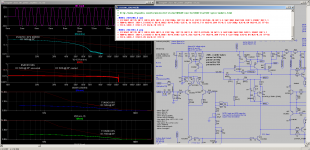
Attached the joke driving 2.1R during heavy overload just before current limit starts. The PSU would not be able to deliver such high currents.
Br, Toni
Not sure if this is too far off topic 😉
\\\Jens
Not sure if this is too far off topic 😉
Well, it is essentially a classic Blameless style amp, as already noted, carefully developed and documented.
The amp has really been built and tested over a reasonable time, with excellent instrumentation.
The simulations are known to match fairly closely with reality, even in the very low distortion.
And Toni has been very helpful with experiments to test claims and ideas.
Seems very on-topic to me.
Best wishes
David
Last edited:
...about a practical view: two 1A 2SC4793/2SA1837 driving 8 pairs of 2SC5200/2SA1943 at +/-70V is a joke from a drivers SOA and even max current perspective.
You need much stiffer drivers (like another pair of 2SC5200/2SA1943) and then there goes your high ULGF.
Toni knows the details far better than I and has already answered the first part, but the second part is of interest because it relates to this whole topic of minimum phase.
If the entire amplifier is indeed minimum phase then slower drivers can simply be compensated for in the faster part of the amp.
The limit to this process is non-minimum phase behaviour, which is what inspired my interest in the first place, where are the limits?
Best wishes
David
Attached the joke driving 2.1R during heavy overload just before current limit starts. The PSU would not be able to deliver such high currents.
Br, Toni
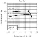
Ummm... is very late here, will take a closer look tomorrow. However, correct me if I'm wrong, is in simulation the 2SC4793 driver maximum collector current (bias plus output devices base current) about 0.2A? That would lead me to the conclusion that in your simulation the output devices would have a beta of 32A/(2*0.2A)>80 (at Ic=32/8=4A). That's about double what the 2SC5200 data sheet guarantees as a minimum (35 at Ic=7A). What is your 2SC5200 model, and how good does it sustain beta with Ic?
As you said, in practice it's probably the power supply collapsing that is protecting your drivers. I still believe that 8 pairs of bipolar output devices, driving 2ohm at +/-70V supplies, as a design target, need a much stiffer driver.
Toni knows the details far better than I and has already answered the first part, but the second part is of interest because it relates to this whole topic of minimum phase.
If the entire amplifier is indeed minimum phase then slower drivers can simply be compensated for in the faster part of the amp.
The limit to this process is non-minimum phase behaviour, which is what inspired my interest in the first place, where are the limits?
Mr. Zan, obviously I am not able to bring any technical or common sense arguments supporting the fact that audio amplifiers are minimum phase systems. I am sure that with a little imagination it can be also proved that audio amplifiers are time variant systems, a subject good for yet another Linear Audio article.
Therefore I'll drop it here and concede that audio amplifiers are whatever you want, or believe, them to be. Good night.
Dear Mr Self,
In the past we have already discussed this matter. Now you are giving the same answer again. C17 (together with R38) is not meant as a replacement of the traditional Miller compensation cap and is not meant to stabilize the global FB loop (as for the latter, these caps are located elsewhere). Instead, the purpose of C17 is to stabilize the Miller loop itself. Obviously, the value of this shunt capacitor should be much much lower and certainly not a huge 44nF.
Cheers, E.
Thank you Edmond. You explained it so much better than I could.
BR Damir
...
That would lead me to the conclusion that in your simulation the output devices would have a beta of 32A/(2*0.2A)>80 (at Ic=32/8=4A). That's about double what the 2SC5200 data sheet guarantees as a minimum (35 at Ic=7A). What is your 2SC5200 model, and how good does it sustain beta with Ic?
As you said, in practice it's probably the power supply collapsing that is protecting your drivers. I still believe that 8 pairs of bipolar output devices, driving 2ohm at +/-70V supplies, as a design target, need a much stiffer driver.
The models BF value has been set to 79. Minimum beta of 80 is guaranteed for a current of 1A. Minimum beta of 35 is guaranteed for a current of 7A. Output current protection of amplifier starts at about 35A. 35/8 ~ 4.4A. So the minimum beta is far higher as 35.
Attachments

Last edited:
The models BF value has been set to 79. Minimum beta of 80 is guaranteed for a current of 1A. Minimum beta of 35 is guaranteed for a current of 7A. Output current protection of amplifier starts at about 35A. 35/8 ~ 4.4A. So the minimum beta is far higher as 35.
Thank you for confirming my findings. Designing by the data sheet curves is not a good idea, since they usually show typical performances rather than the worst case (which should be considered when it comes to delicate things like SOA).
Could you please post the 5200/1943 models you used in simulation? They may have unrealistic sustained beta at high currents. Few free models for power devices are implementing correctly the beta drop.
...
Could you please post the 5200/1943 models you used in simulation? They may have unrealistic sustained beta at high currents. Few free models for power devices are implementing correctly the beta drop.
Attached SOA simulation using BF=35 for 2sc5200_k and 2sa1943_k.
Attachments
I suspect the answer is that at these subsonic frequencies the global NFB is maximal and that covers up a multitude of thermal sins.
That is certainly the case I think; BUT that also means that a less-than-precise bias setting (or a small bias drift long-term) also doesn't have a measureable/audible effect.
Jan
Attached SOA simulation using BF=35 for 2sc5200_k and 2sa1943_k.
Thank you. These are at 25 degrees. Now derate the SOA curves for a realistic operating temperature (say Tc=75 degrees) and see where your driver SOA stands. You can't rely on 25 degrees at those high powers as a design target.
Even this has been taken into account. Don't forget we have more as the minimum BF=35 as the max current per ttc5200/tta1943 can't exceed 4.4A due to current protection.Thank you. These are at 25 degrees. Now derate the SOA curves for a realistic operating temperature (say Tc=75 degrees) and see where your driver SOA stands. You can't rely on 25 degrees at those high powers as a design target.
Even this has been taken into account...
Not to mention that your load lines are DC, some extra factor for the transient nature of excursions.
At worst, just don't use bottom-of-the-bin transistors.
Best wishes
David
Thank you. These are at 25 degrees. Now derate the SOA curves for a realistic operating temperature (say Tc=75 degrees) and see where your driver SOA stands. You can't rely on 25 degrees at those high powers as a design target.
... also to be noticed: if junction temperature of ttc5200/tta1943 rises they have increased beta ...

New thread for the OT discussion is here,
http://www.diyaudio.com/forums/solid-state/260452-non-minimum-phase.html
That is certainly the case I think; BUT that also means that a less-than-precise bias setting (or a small bias drift long-term) also doesn't have a measureable/audible effect.
Jan
If you mean the bias of a Class-A stage then I'm sure that's right. The disturbance is purely at a subsonic frequency which should be suppressed into invisibility by the high level of NFB at low frequencies.
But in a Class-B output stage, bias shift/drift would bring in crossover distortion which is imperfectly linearised by the much lower levels of NFB available at high audio frequencies.
Dear Mr Self,
In the past we have already discussed this matter.
Hello Edmond. Could you point me to this previous discussion?
Now you are giving the same answer again. C17 (together with R38) is not meant as a replacement of the traditional Miller compensation cap and is not meant to stabilize the global FB loop (as for the latter, these caps are located elsewhere). Instead, the purpose of C17 is to stabilize the Miller loop itself. Obviously, the value of this shunt capacitor should be much much lower and certainly not a huge 44nF.
Cheers, E.
Not sure I follow you here. To me the "Miller loop" is the innermost NFB loop that basically turns the VAS into an integrator, which is stable of itself. I think you must be using the term differently?
I understand..... and many other makes, models and brands have been using similar designs for a long time and are stable, also. This forum however, makes it seem like a difficult task without sophisicated testing and SIM and great insight into circuit behavior.
Please give us/me the place and point where simple equations will yield low distortion and stable operation, again.
THx-RNMarsh
Well, that's a major theme of APAD6... The equations for input stage transconductance and VAS gain are extremely simple. Use them to get an NFB factor of about 29 dB at 20 kHz in a Blameless configuration and I would say that low distortion and stability are guaranteed. What more could you ask?
If you mean the bias of a Class-A stage then I'm sure that's right. The disturbance is purely at a subsonic frequency which should be suppressed into invisibility by the high level of NFB at low frequencies.
But in a Class-B output stage, bias shift/drift would bring in crossover distortion which is imperfectly linearised by the much lower levels of NFB available at high audio frequencies.
No I meant a class-B (or even AB). How critical is the exact bias setting?
I would think deviations from the optimal setting of say 5% would not be audible? In one of my tests I changed the bias of a class AB amp from +5% of optimum to -5% of optimum and could hardly see any change in the distortion residual, although the THD value did move a few digits on the far right.
It also reminds me of some posts you read here that after a long and hard journey someone succeeds to lower his amps THD from say 0.0018 to 0.0016.....
Jan
Dear Mr Self,Hello Edmond. Could you point me to this previous discussion?
Sure, it started about here.
No, I'm not using the term differently. We are talking about a different circuit, to be more specific, the power amp of Damir (post 451). This one uses output inclusive compensation (OIC). That means that the Miller loop encloses several gain stages (VAS, driver & OPS) instead of just one (the VAS). Such an integrator is (almost always) not stable of itself and needs additional measures to tame it. That's purpose of C17, compensation of the compensation loop, so to speak.Not sure I follow you here. To me the "Miller loop" is the innermost NFB loop that basically turns the VAS into an integrator, which is stable of itself. I think you must be using the term differently?
Cheers, E.
- Status
- Not open for further replies.
- Home
- Amplifiers
- Solid State
- Your opinions are sought on Audio Power Amplifier Design: 6th Edition. Douglas Self