I am a bit afraid of cross-conduction at >20kHz, there is no way to switch off the transistors fast enough.
I am sorry I have not read your 6th edition, I have the 4th edition.
I am sorry I have not read your 6th edition, I have the 4th edition.
What kind of issues? Too severe to be worth trying?
Maybe Jan has some more info about it - I'm already awaiting his next publication 🙂
Try to search the forum for BIGBT
I made a lot of amps with BIGBT output stage, no problems at all.
I heard that few high-end amps were built with BIGBT lately, in Germany also. 😉
Anybody built something like that Bryston? How hard is it to get the bias control stable?
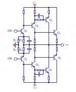
I have built this configuration a number of times in different designs (VFAs and CFAs). No problem with quiescent current. It is slightly different for PNP and NPN devices (within 5%), but no problem with stability.
No beta matching. Tested and measured up to 1 MHz.
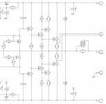
Coil at the output is 1 uH, not 1 mH - it's a typo at my diagram.
Cheers,
Valery
Attachments
Last edited:
I use similar design before and it osc at clipping. Might be different C comp use... will ask the engineers to look into it if you dont have such osc problems.
THx-RNMarsh
THx-RNMarsh
I use similar design before and it osc at clipping.
Deep clipping does not look nice in a sim.
Attachments
In my designs clipping happens at earlier stages. OPS never clips...
I will check it though - thanks for pointing out.
I will check it though - thanks for pointing out.
I use similar design before and it osc at clipping. Might be different C comp use... will ask the engineers to look into it if you dont have such osc problems.
THx-RNMarsh
Hey Richard, one hour ago you said "Ditto, I'm out of here". This is a really fast comeback.
Welcome back anyhow!
Cheers, E.
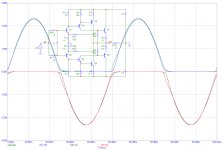
Not sure what Jan has simulated, I know something like this:
Close: Bryston 3B. I haven't simulated it - its from a book I am working on.
Jan
Attachments
Hello Jan.
I'm having trouble understanding your graph. Maybe I'm being dim, but it seems to show the device currents shooting up at the voltage zero-crossing, rather than dropping to zero.
It shows the device currents approaching cut-off, as in class B, but not quite, there remains a small current so they are not completely cut off. So it is the take-over from one device to another, in the next quadrant, that is shown.
It is zoomed to the crossover/takeover point, in reality the shown output sine wave would be way off the scales.
jan
Temperature stability and possible local oscillations. To me, well engineered 2EF with multiple pairs is better solution.
Yes you may have local oscillations, as in any tight feedback loop. But otoh it is an extremely linear structure, keep it in class A and you have one hell of a driver stage.
Edit: you need to keep it in class A because there is no base charge suck-out provision to turn the final transistor off fast.
Jan
Last edited:
Hey Richard, one hour ago you said "Ditto, I'm out of here". This is a really fast comeback.
Welcome back anyhow!
Cheers, E.
I didnt realize where i was at... thought it was the other forum somewhere..... sorry. [tip-towing away]
-Richard Marsh
It shows the device currents approaching cut-off, as in class B, but not quite, there remains a small current so they are not completely cut off. So it is the take-over from one device to another, in the next quadrant, that is shown.
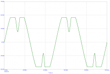
This is my simulated results.
Attachments
This is my simulated results.
Pavel, do those 4 lines represent 4 output devices? Would be good to know which one is where...
Can you please mark them?
Last edited:
Valery, please check the image (you need to open it) - all the info you are requesting is there in the plot description and pasted schematic. Frankly, I would appreciate some independent thinking 😉
Valery, please check the image (you need to open it) - all the info you are requesting is there in the plot description and pasted schematic. Frankly, I would appreciate some independent thinking 😉
Ah, now I see, thank you 😉
This is my simulated results.
This one is 20KHz. It's going to become more interesting at 200-500 KHz 🙂
No you don't, BIGBT you should. 😉
Andrej, no need to mention - I like it a lot, especially "SSA High Performance" one 😉
Andrej, no need to mention - I like it a lot, especially "SSA High Performance" one 😉
TSSA is better. 😉
BIGBT is symmetrical, Bryston is not. Driver's Ib causes difference in pos/neg half.
- Status
- Not open for further replies.
- Home
- Amplifiers
- Solid State
- Your opinions are sought on Audio Power Amplifier Design: 6th Edition. Douglas Self