the current and voltage are 90º out of phase.
Yes, you're right, it's more like 90degrees and not 45. My mistake.
In reality though, since the transformer isn't alone and unloaded, the current profile over time would be some combination of the cap bank charging and the transformer's magnetization, so the sweet spot needs to be found for best result. It's very unlikely to be something like 90degrees...
This means that if you turn the current on at the zero crossing, you get the worst case inrush current.
Exactly! But detecting something other than the zero crossing is really not practical, but it's quite easy with those opto-couplers, so the zero crossing detection is the obvious best choice of thing to do, but then the program needs to apply the appropriate delay after that.
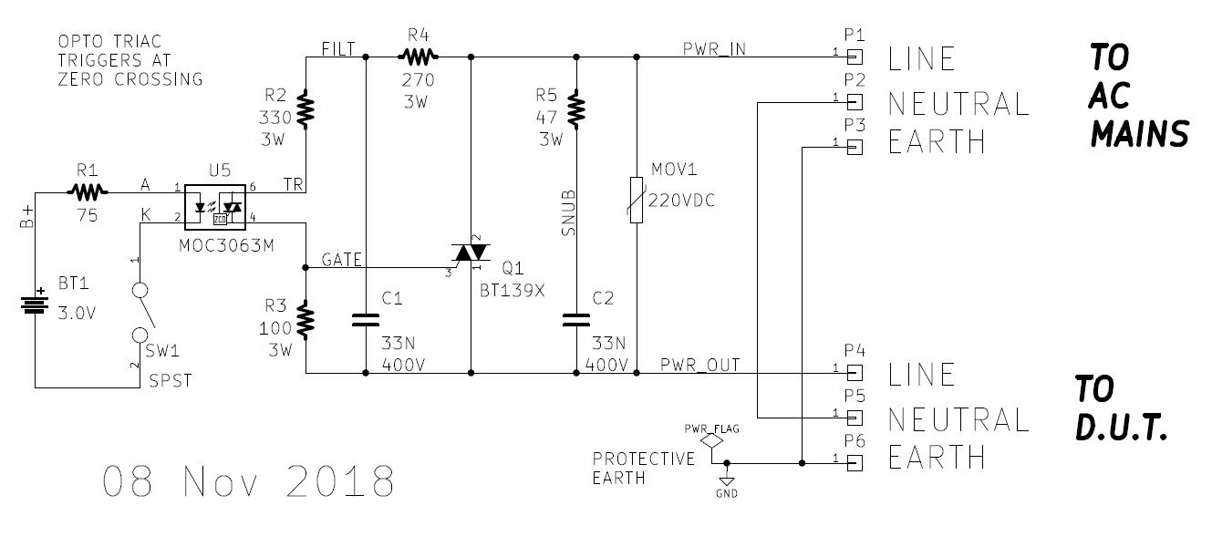
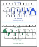
For testing purposes you often want the maximum possible inrush current so you can make worst-case measurements. Certainly I did, when I built and used this inrush current tester. So I intentionally designed the circuit to turn on the triac ("Q1") right at the zero crossing ... as per "ELI the ICE man" . Click the image to see it full size
Discussion and additional images are included in post #41 of the original thread
BTW if you look really, really closely you can see the ±1.2V dead zone, created by the triac's on-state voltage (spec named "VT" in the datasheet). Of course, if you include a bypass relay, the dead zone completely disappears after the relay contacts close. And if you don't include a bypass relay (a la Bryston), read what Bob Cordell has to say about it (2nd edition p. 459).
In reality though, since the transformer isn't alone and unloaded, the current profile over time would be some combination of the cap bank charging and the transformer's magnetization, so the sweet spot needs to be found for best result. It's very unlikely to be something like 90degrees...
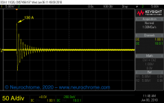
True. In measurements of the inrush current of an 1 kVA toroidal power transformer, I saw currents of 200 A peak with the transformer unloaded and 130 A peak when the transformer was loaded by a 2x45000 uF cap bank.
I've attached the plots here. You can read the rest of the story here: The Ultimate Guide to Soft Start Design – Neurochrome
I used a circuit similar to the one Mark showed above to turn the power to the transformer on at the zero crossing for the measurement of the transformer's inrush current.
Needless to say, I fully support the use of soft start circuits. Even smaller transformers draw significant inrush current. Just make sure you design the inrush limiter such that it can handle the energy of both the cap bank and the energy needed to magnetize the transformer.
Tom
Attachments
Last edited:
Hi,
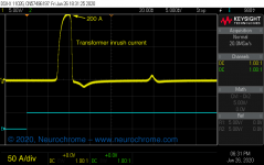
For you information attached it is a timing drawing showing how I control the firing of the triac to ramp the AC as it is done when powering an amplifier ON/OFF. The triggering of the traic it is done using the zero crossing as a sync to fire the triac on. As shown in the drawing the firing of the triac start at 90 degree and it is fired in both side in the positive side and in the negative side of the sine wave and moving the firing pulses that trigger the triac toward the 45 degree of the sine wave. At 45 degree the triac it is turn on full time.This also it is done in reverse when powering the amplifier off. Also if you want to slow down the ramp them your fire the traic 3 to 6 times at the same angle. I used in my system 3 times. In other word your are slowly ramping the AC to prevent the inrush current at the same time slowly charging the capacitors in the secondary side. The more you firing the traic at the same time the slowly it is the ramp. Hoped this clarified and have an idea how using a micro and the zero crossing the ramping of the AC can easily be done. As you can see your are using the micro in the same way you are using a dimmer to control a light bulb or to control the speed of a fan. I have been using this method for almost 6 years without one single problem or break dwon.
For you information attached it is a timing drawing showing how I control the firing of the triac to ramp the AC as it is done when powering an amplifier ON/OFF. The triggering of the traic it is done using the zero crossing as a sync to fire the triac on. As shown in the drawing the firing of the triac start at 90 degree and it is fired in both side in the positive side and in the negative side of the sine wave and moving the firing pulses that trigger the triac toward the 45 degree of the sine wave. At 45 degree the triac it is turn on full time.This also it is done in reverse when powering the amplifier off. Also if you want to slow down the ramp them your fire the traic 3 to 6 times at the same angle. I used in my system 3 times. In other word your are slowly ramping the AC to prevent the inrush current at the same time slowly charging the capacitors in the secondary side. The more you firing the traic at the same time the slowly it is the ramp. Hoped this clarified and have an idea how using a micro and the zero crossing the ramping of the AC can easily be done. As you can see your are using the micro in the same way you are using a dimmer to control a light bulb or to control the speed of a fan. I have been using this method for almost 6 years without one single problem or break dwon.
Attachments
Interesting idea. Did you measure the primary current with your "dimmer soft start"? It would be interesting to compare it with an NTC-based inrush limiter.
If you don't have a current probe, you can build one pretty cheaply from a current transformer: The $10 Current Probe - How to Measure Current with an Oscilloscope – Neurochrome
Tom
If you don't have a current probe, you can build one pretty cheaply from a current transformer: The $10 Current Probe - How to Measure Current with an Oscilloscope – Neurochrome
Tom
There are quite cheap LEM parts readily available nowadays due to their use in mass-produced smps - and they make excellent isolated interfaces to connect to a scope or soundcard/software spectrum/scope - not just for mains current assessment but also audio signals like anode or screen currents in valve amp output stages.
Tom's preference is to use a switch contact to finally bypass any electronic switch device - which is often missed as important for valve amp use, where mains current is best conducted for the full cycle rather than incur some minimum phasing requirement (unless all secondary side loads are rectified with capacitor filter inputs).
Tom's preference is to use a switch contact to finally bypass any electronic switch device - which is often missed as important for valve amp use, where mains current is best conducted for the full cycle rather than incur some minimum phasing requirement (unless all secondary side loads are rectified with capacitor filter inputs).
Hi,
Yes, I did when starting the project. Attached it is the link of my thread " Preventing the inrush current saturation in a toroidal/EI transformer ". In the link I explain all the problems encountered during the develop of the project.
Some of the members helped me to solved some of the problems. In the thread #40 show some pictures one was the current probe but I do not remembered which color was the current.
http:// Preventing the inrush current saturation in a toroidal/EI transformer
I forget to mentioning that this method it is idea for powering tubes amplifier. Tried it in a dynaco tube tuner and when powering up you do not see the flashing in the tubes filaments. As you know the tube filament when cold it is at the lowest resistance and when the voltage it is applied the filament light up very bright. I think by using this method the life of the tube filaments can be extended by suppressing the stress when powering on the amplifier .
Doesn`t this generate Conductive and Radiated noise?Hi,
For you information attached it is a timing drawing showing how I control the firing of the triac to ramp the AC as it is done when powering an amplifier ON/OFF. The triggering of the traic it is done using the zero crossing as a sync to fire the triac on. As shown in the drawing the firing of the triac start at 90 degree and it is fired in both side in the positive side and in the negative side of the sine wave and moving the firing pulses that trigger the triac toward the 45 degree of the sine wave. At 45 degree the triac it is turn on full time.This also it is done in reverse when powering the amplifier off. Also if you want to slow down the ramp them your fire the traic 3 to 6 times at the same angle. I used in my system 3 times. In other word your are slowly ramping the AC to prevent the inrush current at the same time slowly charging the capacitors in the secondary side. The more you firing the traic at the same time the slowly it is the ramp. Hoped this clarified and have an idea how using a micro and the zero crossing the ramping of the AC can easily be done. As you can see your are using the micro in the same way you are using a dimmer to control a light bulb or to control the speed of a fan. I have been using this method for almost 6 years without one single problem or break dwon.
Secondly with the cycle trigger for short duration the challenge is to excite the large transformer.
tauro0221 - the generic heater flashing that occurs for some tubes at power turn on has afaik no valid concern with shortening tube life - so it is just your perception, and perhaps a certain level of forum perpetuated myth.
Hi,
The trigger pulse it is used only to fire the triac once the triac start it will keep on until reach the zero crossing. What you doing it is starting the transformer primary voltage slowly from zero to whatever it is the incoming voltage. I did a test by firing the triac at 60 degree and let run there for few minutes and nothing happened. For me your are regulating the transformer voltage output by controlling the primary voltage. I do not see any noise since once the power it is turn on I bypassed the triac using a relay contact. Why because the triac will keep turning on/off every time that goes thru the zero crossing and that may cause electric noise. About the noise the AC SSR they have nose suppression built into the module. In the prototype used a homemade but added the noise suppression. Hope answered your questions.
The trigger pulse it is used only to fire the triac once the triac start it will keep on until reach the zero crossing. What you doing it is starting the transformer primary voltage slowly from zero to whatever it is the incoming voltage. I did a test by firing the triac at 60 degree and let run there for few minutes and nothing happened. For me your are regulating the transformer voltage output by controlling the primary voltage. I do not see any noise since once the power it is turn on I bypassed the triac using a relay contact. Why because the triac will keep turning on/off every time that goes thru the zero crossing and that may cause electric noise. About the noise the AC SSR they have nose suppression built into the module. In the prototype used a homemade but added the noise suppression. Hope answered your questions.
Hi,
The trigger pulse it is used only to fire the triac once the triac start it will keep on until reach the zero crossing. What you doing it is starting the transformer primary voltage slowly from zero to whatever it is the incoming voltage. I did a test by firing the triac at 60 degree and let run there for few minutes and nothing happened. For me your are regulating the transformer voltage output by controlling the primary voltage. I do not see any noise since once the power it is turn on I bypassed the triac using a relay contact. Why because the triac will keep turning on/off every time that goes thru the zero crossing and that may cause electric noise. About the noise the AC SSR they have nose suppression built into the module. In the prototype used a homemade but added the noise suppression. Hope answered your questions.
can you please share the schematic of the above application?
After looking at a bunch of soft start circuits I decided to design one according to my beliefs as to what is the best way to do it. It may be completely different from your beliefs but there it is.
I wanted a separate power supply for the soft start circuit so it could be used to turn the amp on and off and the powering up of the amps large transformer would not interact with the circuit. The transformer has a dual primary so it can be used for 115 and 230 VAC. There is a surge suppressor, R1, across the transformer input as well as a small high voltage capacitor to filter out RFI on the line from coming into the amp. The power supply always draws a few milliamps, it powers a multicolor LED that emits red with the amp in standby.
The on/off switch only switches 15 volts DC at very low current so you don’t need a switch that can handle large AC current in-rushes. When switched on, the DC power is sent through a regulator for consistent voltage and time of circuit operation. Relay K1, a small current relay, pulls in and turns on a triac, AC current flows through a couple thermistors in series to limit in-rush current, two 5 Ohm parts for 115 volts to limit the current to no more than 12 amps, or two 10 Ohm parts for 230 volts also limiting to 12 amps. There is a current limiting resistor, R2, at the triac gate and a RC network,R3/C2, over the triac for some protection of the triac.
The circuit uses a voltage comparator, U2, to delay turn on of a relay, K2, which bypasses the thermistors, I do not like to have a current limiter staying in the circuit or the heat they generate inside the amp. The voltage comparator has a voltage divider, R8/R9, to set the voltage at 10v as the reference voltage on the positive input. That voltage is compared to the negative input which has an adjustable resistor, R7, which limits the current charging the capacitor, C6, and the rate of charge therefore voltage ramps up quickly, a couple seconds to more than 10 seconds, for the delay. When the voltage on the negative input matches the positive input, the output is turned on. There is a diode, D4, across R7 to give a quick discharge path for C6 so the circuit can reactivate quickly, as in the case of a temporary power loss. R2 limits the current through the comparator which drives the gate of a small MOSFET through a gate resistor, R11. The MOSFET pulls current through a large relay K2 to bypass the thermistors and another small relay, K3, which changes the LED from red to blue to show status ON. There is a Zener diode, D5 and a small capacitor,C7, at the gate of the MOSFET to protect and stabilize it, probably not needed but cheap insurance.
So far, the circuit has been very reliable in a couple power amps with 2400VA and 4000VA toroid transformers with .78 farads to 1.2 farads of storage caps. In small part quantities the soft start board costs around $34 USD.
Attached is the Schematic, BOM and Gerbers. Enjoy.
I have a doubt about this circuit that how the small NTC of each 10ohm from Ametherm that was used in the above circuit is able to deal with about thousands of joules of energy when almost 1F of capacitors are used in the secondary.
Are the two NTCs each 10ohm in series hard limiting the current in to the primary of the transformer?
what is the max peak inrush you have observed / measured with above setup and large caps of 1.2F of storage?
Again, it doesn't matter if you use zero crossing or not once the triac, or relay or whatever starts conducting current you must have something to limit the current. The Ametherm NTC Varistors are excellent for current limiting device, they handle the surges repeatedly without failing.
A single series 995-SL22-5R012 NTC is rated for up to 6.4mF direct on line rectification filtering. The actual amplifier PT will introduce a turns ratio which presumably would increase the allowed maximum filter capacitance (eg. a 60V secondary could feed up to 0.025F). The additional series NTC and effective PT winding impedance would also help, but it is likely that johnhenryharris has not made any design effort in that regard.
Ok as far as I see my max amplifier transformer will be mostly 4KVA with 0.5F per rail caps. So as per what you say the lights wont dim in the house as the NTCs will take care of the current limiting?Again, it doesn't matter if you use zero crossing or not once the triac, or relay or whatever starts conducting current you must have something to limit the current. The Ametherm NTC Varistors are excellent for current limiting device, they handle the surges repeatedly without failing.
If we take the total caps Joules at 80V it will be about 4000J just the caps alone and the transformer might take another atleast not less than 1000Joules so 5kilo joules can be limited by the traic at zero crossing or trigger just above zero crossing is sufficient with two 10ohm ametherm NTCs?
well yes if NTCs can hard limit the current ? then why not but my doubt is all about the Joules capability of the NTC if not.
Can you please post the pics of the PSU of 4KVA and 1.2F cap that you have mentioned and also if you have any pics where the peak inrush current is monitored that will be great or let us know what is the peak inrush is observed after the softstart that you have mentioned in the first post.
I was looking for the pics that were posted in the F5 turbo thread with a rebuild of a Threshold SA/1 clone with the 2.4KVA transformer and .78F of caps, it is in the thread around post 365 or so, the amps with the larger transformer and cap setup is in a commercial amp which I don't have pics of that.
For the Varistors you have to make sure they are spec to handle more current than will flow. So I limit the max in-rush current to 12 amp and the varistor is spec for 16 amps, it is over 1.25" in diameter.
For the Varistors you have to make sure they are spec to handle more current than will flow. So I limit the max in-rush current to 12 amp and the varistor is spec for 16 amps, it is over 1.25" in diameter.
During the 80s I designed 5kW Power Blocks supplied by 3 Toroids each 2kVA. I choosed the NTC/TRIAC solution with a second TRIAC delayed bypass circuit. Triggering TRIACs with optocouplers always resulted in audible hum of the transformers. This can be avoided by replacing pulse triggering by continous triggering. So I added a bank of NE555 timers generating some 30kHz square waves that were fed via small isolating pulse transformers into the gates. This worked like a charm.
Johnhenryharris, are you saying the 10 ohm cold resistance of the two NTC's in series will limit your NTC current to 12A for 120VAC mains supply?
The NTC spec rating says 12A continuous limit up to 65C (ambient), but that relates to a hot thermistor that has a resistance that has dropped to its thermal equilibrium - possibly causing the NTC resistance to settle below 5/100 ohm, for a steady state dissipation of perhaps below 7W.
A cold NTC with 12A starting to flow will dissipate circa 720W, and its resistance will fall rapidly, and so the NTC may well start to conduct higher current than 12A, depending on the short-term current requirement of the PT primary for both in-rush and secondary side capacitance charging.
I strongly recommend you capture a number of in-rush current waveforms for your amp setup with 0.78F cap, to characterise exactly what the current waveform could be. Your application for the NTC's is not 'text book' and so I don't think you can assume compliance with part ratings.
Last edited:
- Home
- Amplifiers
- Power Supplies
- Yet Another Soft Start Circuit