Try it and find out!
Another thing you can do is: Calculate an estimate of the worst possible case inrush peak current, if the primary voltage is 230VAC RMS, and if there is an Ametherm MS35-20010 Inrush Current Limiter in series with the primary. (Its resistance at room temperature is 20 ohms).
Then, after you've got a calculated estimate: assemble that circuit in the lab and actually measure its inrush current! Is the measured inrush more than the estimate? Less? How (in)accurate was your calculation?
A test fixture like the one in post #102 of this thread, might be useful. It arranges to create the worst case inrush every single time the gear is switched on. Just what you want for worst case testing on the lab bench.
Great Input mark thank you very much. Nothing can beat the measurement when it comes to Inrush.
A current is split ,so twice lower , so NTC may be used smaller size with higher resistance ,maybe faster heating or cooling down .
You are over thinking the circuit, keep it simple, turn on with resistance in-line, remove the resistance after a few seconds, nothing else needed.
Are you referring to something simple like the suggestion I made in my post of 30th June; I.E.a non latching push switch with resistor which when operated shorts out the mains switch for a few seconds before operating the mains switch?You are over thinking the circuit, keep it simple, turn on with resistance in-line, remove the resistance after a few seconds, nothing else needed.
Some people just seem to like doing things the hard way.The audiophile fuse brigade seem to ignore advice like replacing fuses with circuit breaker mains switches aswell.
I am just stirring the pot, I see many ideas with chokes, etc, and the thought process is interesting but a lot of the ideas, while interesting, are going way beyond what is needed to power up a power amplifier.
I have found the NTC of sufficient size and correct resistance to be more than adequate, just needed a circuit to take it out of the mains path when it has done enough.
On the circuit breaker note, I remember power amplifiers with the circuit breaker as the on/off switch.
I have found the NTC of sufficient size and correct resistance to be more than adequate, just needed a circuit to take it out of the mains path when it has done enough.
On the circuit breaker note, I remember power amplifiers with the circuit breaker as the on/off switch.
I expect that at least half the people who actually install a soft-start circuit in their audio gear, use a PCB and a circuit design and a "soft start philosophy" designed by someone else. Many builders strongly prefer to buy, rather than create, their PCBs.
I am just stirring the pot, I see many ideas with chokes, etc, and the thought process is interesting but a lot of the ideas, while interesting, are going way beyond what is needed to power up a power amplifier.
I have found the NTC of sufficient size and correct resistance to be more than adequate, just needed a circuit to take it out of the mains path when it has done enough.
On the circuit breaker note, I remember power amplifiers with the circuit breaker as the on/off switch.
The quest is to find one universal solution which fits for all. Consider the OP`s extreme case of almost 1F of caps at take 80V per rail and 4KVA transformer. Which NTC values will be able to deal with that? Take a 4KVA at 230V will have approx 20x the inrush current as the trafo rating will be not less than 17Amps so 20x is about 340Amp just transformer alone and imagine having tons of caps even in secondary which is 1F.
Which values of NTCs can be used in that case?
When it comes to line AC, safety is number one, think will this design pass regulatory?
I feel uneasy about a NTC device cooking away in a fault condition for ever. Can it be run long term safely? Is this how you want to deal with the fault condition?
I have always used a simple and effective method that Pioneer used on many models. It is a 20+W >=3.3 ohm series power resistor sitting on top of a thermal fuse, shunted by the relay contacts. As a extra precaution you can have a heat shield surrounding the power resistor. Run the relay coil off of the transformer secondary using a rectifier and voltage dropping resistor.
It ain’t fancy, but is effective, very reliable, small footprint, cost effective and was a design that passes regulatory, depending on how it is implemented. I use Panasonic 16A relays intended for uwave ovens.
As what OP has recommended the actual inrush current shouldnt go beyond 12Amps for 230V AC. It should be a hard limit. How to put a hard limit is the actual question. Run it for few secs and bypass with relay would be wonderful. This way no matter what kind of load it just hard limits the current to 12A. I thought of using Mosfets but how to limit current since its AC so no idea. Secondly using mosfets in mains is it safe?
The soft start board by jhofland / XRK uses MOSFETs to switch the mains. The ones they have chosen are kinda spendy but designing your own PCB and sending it off to fab isn't exactly cheap either.
<Which values of NTCs can be used in that case? >
If you look at the BOM you will see large NTCs that can hold the in-rush to 12 amps which is safe for home wiring.
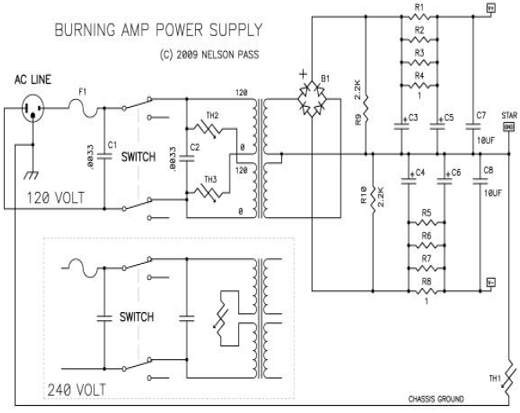
The NTC is rated for continuous use. If you look at the Power supply for the F5T it has a NTC in-line ALL the time. I like to bypass the NTC after the initial in-rush as I do not like adding heat to the inside of the amp, just my preference.
For large power amps I like relays with a contact rating of 30 amps, just for a little added safety and durability.
But each to his/her own, that is why we has a forum for discussion of ideas. Even though I have my own biases I like seeing what others think and have done.
If you look at the BOM you will see large NTCs that can hold the in-rush to 12 amps which is safe for home wiring.
The NTC is rated for continuous use. If you look at the Power supply for the F5T it has a NTC in-line ALL the time. I like to bypass the NTC after the initial in-rush as I do not like adding heat to the inside of the amp, just my preference.
For large power amps I like relays with a contact rating of 30 amps, just for a little added safety and durability.
But each to his/her own, that is why we has a forum for discussion of ideas. Even though I have my own biases I like seeing what others think and have done.
Hard current limit 12 ? I think only three ways are possible there:
1. Measure current with current transformer or small resistor and use some kind of feedback to to control SCR gate angle ,or two mosfets in series ,whatever you prefer and easier to control .
2. Use some NTC in series ,if you want 12Amp max , 230V / 12A = about 20 ohms ,in hot state , in cold their will have even higher resistance and less inrush current .
3. Use fixed resistor about 20 ohms high power , like 25 - 50 W ,it will not heat up so quickly in second or two ,but can withstand overload .
Soft start should be bypassed with relay or SSR, SCR, whatever prefer .
Can be fixed time delay or amplifiers capacitors voltage detector , simple divider and TL431 driving optocoupler from some aux voltage ,or from amplifiers capacitors .In case of fault voltage will be too low and 431 will not turn on optocoupler and soft start will not be bypassed .To prevent resistor overload soft start must have limited operating time , lets say 3 secs .But it may sound not simple ...
NTC resistance is given in cold state, 10 ohms each, 2 in series for 20 ohms for 230V and two 5 ohms for 120v. (the spec also gives hot resistances in the sub ohm)
some of what you mention is cover in the first post of this thread.
some of what you mention is cover in the first post of this thread.
So for (230V) 995-SL32-10015-B resistance changes from 10 ohms when cold to 0,05 ohms when hot ,at 15Amps . I see there a drawback - thermal inertia , if mains voltage gets lost for a second or two , capacitors may discharge , but limiter 32mm (big one) may not cool down and not limit inrush when mains voltage appears again .
Simple solution ,but need to carefully select limiter model according to output capacitors and their charge time ,not to get NTC resistance too low too early ,when capacitors not fully charged yet .I would prefer fixed resistor ,selected for few amperes .In my previous amplifier was 180w rated transformer ,loaded with 10000uf per rail , and when turning on power switch , even lights dimmed for short moment ,no soft start or current limiting was there .
Simple solution ,but need to carefully select limiter model according to output capacitors and their charge time ,not to get NTC resistance too low too early ,when capacitors not fully charged yet .I would prefer fixed resistor ,selected for few amperes .In my previous amplifier was 180w rated transformer ,loaded with 10000uf per rail , and when turning on power switch , even lights dimmed for short moment ,no soft start or current limiting was there .
what you are calling thermal inertia is not an issue. Start up the amp, circuit bypasses the NTC in 3 to 10 seconds, time is selectable, then measure temp of NTC and resistance, didn't get hot enough to change the resistance much. Do repeated power ups and down and check the NTCs, still not an issue.
In the event of a bypass relay failure the NTC will go to low enough resistance to not affect the current flow, a fixed resistor wouldn't do as well in this case.
An amp with a 180VA rated transformer would not need a soft start circuit, IMO.
In the event of a bypass relay failure the NTC will go to low enough resistance to not affect the current flow, a fixed resistor wouldn't do as well in this case.
An amp with a 180VA rated transformer would not need a soft start circuit, IMO.
About thermal inertia - i mean simple solution,used widely, with only NTC resistor , when no bypassing relay present .
You want simple ?
That relais comes in at around 175V~ (without the resistor).
As the NTC gets hot the resistance goes down and the output voltage up.
After a while, when the voltage gets high enough, the relais close the circuit bridging the NTC and holding itself.
With the resistor the threshold can be adjusted to a higher voltage and longer wait.
Mona
Looking for a possible (simple) soft start circuit combined to a small-medium transformer, feeding a class A, I tried this one above but unsuccessfully. Resistor heats a lot and there is too much voltage drop across output. Where was I wrong? Used a Shrack RT424730 and a 80-ohm NTC B57236S080M
You tell me what is your transformer KVA and at what Voltage will be the secondary AC and also the capacitors size in microfarad there is something I can try recommending.
- Home
- Amplifiers
- Power Supplies
- Yet Another Soft Start Circuit