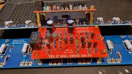
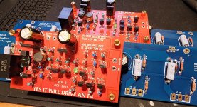
Another F4 with "Yes It Will Drive An F4" boards is born today!
Had a few issues during the build, but all is well now. I'll share those on the F4 build guide forum.
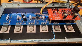
This is a stereo F4 in a 4U/300 Dissepante chassis. Antek AS-3220 transformer, store PSU V3, and my first ever use of @Mark Johnson push button soft start H9KPXG.
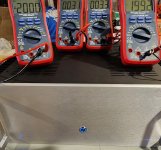
I've got bias and DC offset set at 0.2V and near zero VDC respectively. I've confirmed it plays music on test speakers, but need to hook it up so something better for a true audition.
Thanks to Mark Johnson, 6L6, and ItsAllInMyHead for the great boards, guide, and advice. I also can't forget to thank Papa for an amazing amp design.
Looking forward to playing some glorious tunes in the new year.
Happy New Year all!

Had a few issues during the build, but all is well now. I'll share those on the F4 build guide forum.
This is a stereo F4 in a 4U/300 Dissepante chassis. Antek AS-3220 transformer, store PSU V3, and my first ever use of @Mark Johnson push button soft start H9KPXG.
I've got bias and DC offset set at 0.2V and near zero VDC respectively. I've confirmed it plays music on test speakers, but need to hook it up so something better for a true audition.
Thanks to Mark Johnson, 6L6, and ItsAllInMyHead for the great boards, guide, and advice. I also can't forget to thank Papa for an amazing amp design.
Looking forward to playing some glorious tunes in the new year.
Happy New Year all!
Attachments

Last edited:

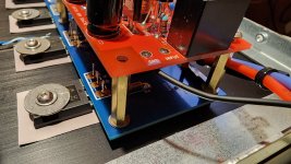
The power relay/soft start has a little shelter and just peaks it's head out enough to access the AC mains side for the terminal block access.
It works great by the way! Thanks Mark!!!


It works great by the way! Thanks Mark!!!
Last edited:
Very nice looking build. Now some comments from the Receiving Inspection and Warranty Service Depts.Another F4 with "Yes It Will Drive An F4" boards is born today!
Had a few issues during the build, but all is well now. I'll share those on the F4 build guide forum.
This is a stereo F4 in a 4U/300 Dissepante chassis. Antek AS-3220 transformer, store PSU V3, and my first ever use of @Mark Johnson push button soft start H9KPXG.
I've got bias and DC offset set at 0.2V and near zero VDC respectively. I've confirmed it plays music on test speakers, but need to hook it up so something better for a true audition.
Thanks to Mark Johnson, 6L6, and ItsAllInMyHead for the great boards, guide, and advice. I also can't forget to thank Papa for an amazing amp design.
Looking forward to playing some glorious tunes in the new year.
Happy New Year all!
View attachment 1401202
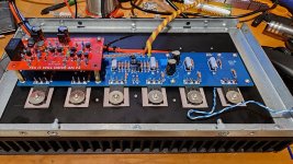
(1) Did you shrink wrap the outputs? Did you make a long cable and then cut it to length when building the case? It's nice how tidy the wiring looks and apart from other wires.
(2) I assume this is SE only inputs. How are the inputs wired? I only see the hot wired to the FE board ( black wire ).
(3) There is no room for taking apart the front and back and sides... it'll be hard to change the front panel power BLUE to red or white... or just to change it. You need at least one inch of space to pull out the connector to the soft turn on switch. And that's a hard twist to the wires.
(4) The Left and Right LEDs to the front panel are a nice touch. Some day some one will build one such amp with color changing LEDs so it can be used as a power level indicator... you know.... red at low power... white at mid power and blue at high power... How do you hold those LEDs in place? I think they will pop out in travel without some mechanical back plate. Plain friction won't hold them. trust them... UPS/Fedex WILL knock them out. I don't know how they do it, but I guess dropping things from 6 feet is part of their handling regime.
(5) Now I don't build these big ones, but I've had to take some apart to repair shipping destruction by UPS and Fedex... (*) My "repair" observation would be that giving some slack to the wires going about helps a lot when you have to pull out some sides to reinstall handles, missing panel screws... even the shaking between the doughnut and the back of the soft turn on will break it.... I'm concerned that the doughtnut might shake a little while "
(6) How about using push in Molex connectors to the boards? It will allow you to keep the wires short and yet it will be easy to take the box apart for repairs.... and it will make the construction and build testing easier with a prebuilt harness.
(*) Heck, my first DIY amp purchase was a pair of Rawson mono block F5s. One of them didn't work because a wire came almost loose and it caused an intermittent connection. Ever since I always open amps when I receive them to inspect them before powering them up. I could pass for Receiving Inspection now. For F5s pay special attention to the "flying" thermal sensor that sits on the heat sink... push it down to make sure it didn't come off the heat sink... even just barely will smoke parts.
Last edited:
(1) --> I used a standard twist and heat shrink technique (drill, pliers, 3:1 heat shrink) to keep some of the wires tidy where it made sense. Speaker outputs are twisted and heat shrinked. Due to the layout and how the other wires connect, it didn't make sense to me to twist much else on this build.
(2) --> SE only. I used Mogami W2381 (black "single" wire with grounded shield, so dual conductor) for the RCA to YIWDAF4 input. I used heat shrink twisted 28Ga silicone insulated wire for the ~3" from the YIWDAF4 output to the F4 input.
(3) --> Surprisingly, taking the front or back off is very easy. Both are easily accessible for a screwdriver. The LED's are just press fit heat shrinked (3x) into the holes {thanks to @Mark Johnson for that idea vs using my old standard hot glue}. Grounds are bolted to chassis. The switch can be removed if needed by snipping the zip ties and unscrewing from the H9KPXG terminal blocks. No de-soldering required.
(4) --> I don't plan to take apart the amp, so I went for tidy wiring. If it did need to be disassembled (I did put it together and disassembled it more times thank I'd like to admit for various errors and a few troubleshooting efforts before biasing yesterday), everything can be "unplugged" as at least one side of each wire connecting is easily dis-connectable (spades or screw terminals). There's ample room between parts that they will not impact one another sitting on a shelf, or the back of your civic on a washboarded dirt road. If you drop it from 5ft up, like UPS does, I still don't see the transformer contacting anything without completely braking free (which is unlikely since it's held in by a steel strap to a steel perforated plate). If you go all Mythbusters and see how high it can fall before it breaks free, then my guess is 8 foot fall, but I"m not going to confirm that
(5) --> Molex would likely work well as long as they are rated appropriately. I just use the spade connectors on one end of the wire connections and solder directly to PCB on the other. Same intent is met as Molex for <1/10th the cost. I don't have that Orange County salary, so I find it prudent to be frugal where it makes sense to me.
Thanks for all the pictures. It really adds to the thread. I offer a couple of things ; I am not sure whether they are good ideas but I am curious for input ;
i. the adoption of two core shielded for signal wires; the typical use of single core shielded `microphone cable' neglects that the outer sheath is `return' and not chassis ground. My impression is that noise on the return is still noise on the signal path... A better approach might be two cores and a separate shield connected to chassis ground.
ii. twist the DC feed +ve,-ve and GND from cap bank to boards.
The lure of a separate `PSU box' with SMPS based supplies within seems to get more attractive every time I sit down and think about placement of parts, wire routing, wire choice, etc. It appears to dumb down the many potential problems presented by the more traditional form of `everything in one box'.
I strive (and typically fail to achieve), such neatness. I haven't tried the drill twisting routine yet, but your care and thought clearly shows in the well separated routing and placement of assemblies.
👍
(1) --> I used a standard twist and heat shrink technique (drill, pliers, 3:1 heat shrink) to keep some of the wires tidy where it made sense. Speaker outputs are twisted and heat shrinked. Due to the layout and how the other wires connect, it didn't make sense to me to twist much else on this build.
(2) --> SE only. I used Mogami W2381 (black "single" wire with grounded shield, so dual conductor) for the RCA to YIWDAF4 input. I used heat shrink twisted 28Ga silicone insulated wire for the ~3" from the YIWDAF4 output to the F4 input.
(3) --> Surprisingly, taking the front or back off is very easy. Both are easily accessible for a screwdriver. The LED's are just press fit heat shrinked (3x) into the holes {thanks to @Mark Johnson for that idea vs using my old standard hot glue}. Grounds are bolted to chassis. The switch can be removed if needed by snipping the zip ties and unscrewing from the H9KPXG terminal blocks. No de-soldering required.
(4) --> I don't plan to take apart the amp, so I went for tidy wiring. If it did need to be disassembled (I did put it together and disassembled it more times thank I'd like to admit for various errors and a few troubleshooting efforts before biasing yesterday), everything can be "unplugged" as at least one side of each wire connecting is easily dis-connectable (spades or screw terminals). There's ample room between parts that they will not impact one another sitting on a shelf, or the back of your civic on a washboarded dirt road. If you drop it from 5ft up, like UPS does, I still don't see the transformer contacting anything without completely braking free (which is unlikely since it's held in by a steel strap to a steel perforated plate). If you go all Mythbusters and see how high it can fall before it breaks free, then my guess is 8 foot fall, but I"m not going to confirm that
(5) --> Molex would likely work well as long as they are rated appropriately. I just use the spade connectors on one end of the wire connections and solder directly to PCB on the other. Same intent is met as Molex for <1/10th the cost. I don't have that Orange County salary, so I find it prudent to be frugal where it makes sense to me.
Funny, I just got Mogami balanced cables. Nice how tidy it is.
Are spades better than Molex?
Heat shrinked? Aaahh... that's clever. I think next time I open any amp I'll do just that mod. Thanks.
Front switch vs. doughnut. The funny thing is that I got shipped an F4 with the same parts as yours, except the doughnut lays flat and very tight - it doesn't move at all. The power switch is the same, and it had more space but the wires did have a similar twist as yours.... so the issue is not the doughnut moving but perhaps some strain imposed by the tight turn of the wires caused by routing them around the doughnut.
Anyhow, UPS somehow broke (sheared) the plastic backing of the switch ( it's a two piece jobbie ). I have no clue how they did that, as the box didn't show damage otherwise. They must have dropped it, flat, and the force of the "stopping" must have done some serious G's on the box. Incredible, and the box had the usual "Fragile" sign... which for UPS must mean "made in Italy", I guess.
I still would like to see a preferred mounting method for the "standard" cases so we could have a prebuilt wiring harness. That, IMHO, is my biggest challenge. How to do the wiring tidy and clean. You know, like when you buy the NCore kit, they sell you the wiring harness too. Maybe the board layout could take that into consideration.
OC Salary? I work remote ( VPN access to the labs, license servers and Git repos ), you could be charging what I charge and live in the Puget Sound... which is not that much cheaper nowadays.
Frugal? Let's face it, in DIY you save a ton of money over the commercial version. I was talking to a local guy yesterday that has a history of $50K components and knows local audiophiles that have systems worth almost a mil... He does his by buying "used" five figure components and then turning them over in six months or so... that way he'd never spending tons of money, yet, he likely has six figures at any one time on his stuff. That, is not for me, OC or not. I guess I'm too cheap or maybe I know what the Bill Of Materials is... and the labor is my hobby. So, I don't much stick around those people. He showed me pictures... one of his friends is into the Audiophile Ethernet Switch stuff.
I wonder if I have some Mpingo discs around. I think the F4 needs a few of those...
Nice job.
Last edited:
Whoever decides to design the next "Yes It Can Drive an F4" circuit, is probably going to include some kind of negative phase 2nd harmonic feature, or at least that's my guess. The F4 itself is amazingly neutral, and "ruthlessly revealing" as Nelson Pass puts it. So it would be completely unsurprising if someone took in upon themselves to create a drop-in front end card for the F4 which added the euphonic coloration known as negative phase 2nd harmonics, to give the F4 some "Personality". Perhaps with a PCB jumper which enables and disables the euphonic coloration.
not me of course, I've already contributed the (first) YICDAF4 presented in post #1.
not me of course, I've already contributed the (first) YICDAF4 presented in post #1.
Hmm... just put a B1 in front of it... or maybe a B1K. Just put it in front of the YICDAF4. More boxes, more wires!
A tube preamp with 20V output handily drives the F4.
A tube preamp with 20V output handily drives the F4.
Last edited:
An op amp will easily drive a F4
So will a 6922 or buffered 12ax7
There are many solutions to driving that amp.
So will a 6922 or buffered 12ax7
There are many solutions to driving that amp.
D
Deleted member 544066
I just finished installing the YICDAF4, but i get some hum from both channels, left side slightly worse. Any ideas? Did I wire incorrectly?

Just some observations.... those super long transformer secondary wires always give me the heebie jeebies. Huge nasty current pulses there (green and blue wires). I like short, twisted, and as far far away from everything as possible. Note where the rectifier blocks are located in the factory First Watt amplifiers. This is not an accident. Low level signal wiring (RCA to YICDAF4, YICDAF4 to F4) should be small (24 to 28 gauge solid wire, tight twist) or mini coax. Again short runs, and away from everything else much as possible. Distance is your friend. Rather than wire insanity and a box full of antennas..... you really need: tidiness, neatness, twisted wires, and lots of distance / proximity. I would focus on just one channel at a time. Un-power the other one. Short the RCA input connector during the process so that you are isolating the amplifier channel from any outside influence. See if you can get just the one channel silent with some re-work and the new thinking / approach. With that success achieved, re-connect the other channel and see where you're at....
Attachments

Quick question. Like the bone head that I am I inadvertently installed Q12 backwards on one of my boards and fried it on startup. I removed it and it tests dead with my transistor tester. I do have a couple of BC546B in my spare parts bin, Hfe= 430, Ube=695mV, IV=6.2mA. can I substitute a BC546B for the BC546C in this circuit. Thanks
I would say your replacement there looks fine for the current source. Maybe Mark will drop in and confirm.
As the title of this Forum thread reminds us, this board uses tightly matched bipolar transistors. In fact, tightly matched BC546C transistors -- Q5 and Q9 on the schematic and PCB silkscreen.
I would imagine that you had to test at least 16 or 20 BC546C's, to get two tightly matched pairs. One pair for the left channel and one pair for the right channel. So that leaves at least 12 other BC546C's that didn't give great matches. Why not use one of them for Q12?
I would imagine that you had to test at least 16 or 20 BC546C's, to get two tightly matched pairs. One pair for the left channel and one pair for the right channel. So that leaves at least 12 other BC546C's that didn't give great matches. Why not use one of them for Q12?
Hi Mark,
I got the matched parts as part of a group buy kit , so no spares. I can always order more from mouser but using the B part would save time.
Paul
I got the matched parts as part of a group buy kit , so no spares. I can always order more from mouser but using the B part would save time.
Paul
- Home
- Amplifiers
- Pass Labs
- Yes It Can Drive An F4 -- an example circuit using tightly matched bipolar transistors