I think that is answered in the second sentence of the 1st post of this thread.Will you do a build plan for this? And how to match them?
Best,
Anand.

Not really, there is (1) a matching circuit jig and then there's (2) a FE circuit for the F4.
Those are two different things. You need the matching circuit ( board? ) to match the transistors to build the YICDAF4 board.
Again, two different things.
For the matching, I'll wait for the video to get posted, for the YICDADF4, it looks a little more complicated.
Correct me if I'm wrong.
Those are two different things. You need the matching circuit ( board? ) to match the transistors to build the YICDAF4 board.
Again, two different things.
For the matching, I'll wait for the video to get posted, for the YICDADF4, it looks a little more complicated.
Correct me if I'm wrong.
Remember that Mark’s transistor matcher, presented at BAF’24 also had this project mentioned, as this project uses that transistor matcher. Neat!
So do you need both boards..? Well, yes, but as you were at BAF’24 and saw that presentation, you were handed the matcher board.
😎
So do you need both boards..? Well, yes, but as you were at BAF’24 and saw that presentation, you were handed the matcher board.
😎
Indeed, "Yes It Can Drive An F4" was a little lagniappe tossed in at the very end of my BAF-2024 talk about BJT Simple Matcher. YICDAF4 was presented as a "bonus", an example of a circuit which benefits from matched BJTs. The talk was about how to match BJTs and the bonus at the end of the talk was an application example.
DIYers can build the BJT Simple Matcher all by itself (my BAF presentation slide deck + schematic + Gerber file are found HERE on the Forums); they can choose to completely ignore Yes It Can Drive An F4.
Similarly, DIYers can build Yes It Can Drive An F4 as a standalone project, as long as they match the two input BJTs tightly. It's not mandatory to build or use a BJT Simple Matcher; that is just one cheap and easy way to get matches. No doubt there are a dozen other ways to match BJTs, and a builder is free to use any one of them she likes, as long as you achieve the matching objective printed in boldface text on the schematic of Yes It Can Drive An F4: deltaVBE <= 0.3 millivolts. Post #17 of this thread suggests a way to virtually guarantee success, by spending $5.40 , which I consider cheap.
Remember that Mark’s transistor matcher, presented at BAF’24 also had this project mentioned, as this project uses that transistor matcher. Neat!
So do you need both boards..? Well, yes, but as you were at BAF’24 and saw that presentation, you were handed the matcher board.
😎
I missed that... didn't get the board.
Wanna match 100 transistors? ;-)
OK, I'll read post #17 again.... wait, t hat just tells me to buy a bunch... OK... but still, need to match them, huh? So excuse my green ignorance, but I still need to match them to deltaVBE.....
Sounds like a great opportunity to try ordering boards from one of the board vendors! It’s easy.
Yes it is! I did for the M2X input stage cards, nothing burst into flames AND it was a very educational experience.
If I made it work....anyone can 😉
If I made it work....anyone can 😉
I'm curious, is there a video of that "talk", and any others for that matter available here on these forums?Last month at the Burning Amp Festival, I presented a little PCB called BJT Simple Matcher. That BAF talk...
Not yet but I believe they exist and may be `in post production'. I anticipate they will be put up here:
https://burningampfestival.com/videos/
https://burningampfestival.com/videos/
Obviously there are LOTS of different ways to drive an F4 power amp from a 50mm X 90mm piggy backed PCB; the one in this thread is just the design I happened to show at Burning Amp 2024. All you need to do is devise a way to amplify the input signal and make it swing the front end's output at least ±20V (peak), using ±23V power supplies. Do that and you have succeeded.
Here are a few; I'm sure diyAudio members can think of several more. These are NOT finished and complete, polished circuits ready for immediate implementation; instead, they are preliminary ideas to be explored by ambitious and talented DIYers
* Build a standard and extremely simple gain-of-20 circuit using a high voltage op amp like the OPA-552. The "Marauder" front end card sold in the store uses this exact IC to perform this exact function. Its schematic is on the Forum. There are other high voltage opamps to choose from if you want to do it a little differently.
* Adapt Hugh Dean's "AKSA Lender Preamp with 40V output swing" (link 1) to use bipolar ±23V power supplies instead of a single positive supply
* Tweak the FirstWatt BA3 Front End circuit design (link 2) and reduce or eliminate the heatsinks on the front end card
* Adapt Tomlinson Holman's famous "Advent Receiver Phono Stage" to ±23V power supplies and rip out all the RIAA frequency equalizer stuff; make it a flat frequency response amp. See attached image below
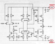
* Adapt John Curl's extremely famous "Levinson JC-2 discrete opamp" to ±23V power supplies, image below. See whether you can get it to swing the output at least ±20V (peak)
* Adapt Wayne Colburn's famous "BA2018 line stage" circuit to fit a 50 x 90 PCB (link 3)
* Adapt any of the other VFET front end cards and/or Ship Of Theseus front end cards, to ±23V power supplies on a 50 x 90 PCB. Dreadnought, Bon Homme Richard, Kitty Hawk, Lexington, Hornet, et al. Go wild.
* etc
Here are a few; I'm sure diyAudio members can think of several more. These are NOT finished and complete, polished circuits ready for immediate implementation; instead, they are preliminary ideas to be explored by ambitious and talented DIYers
* Build a standard and extremely simple gain-of-20 circuit using a high voltage op amp like the OPA-552. The "Marauder" front end card sold in the store uses this exact IC to perform this exact function. Its schematic is on the Forum. There are other high voltage opamps to choose from if you want to do it a little differently.
* Adapt Hugh Dean's "AKSA Lender Preamp with 40V output swing" (link 1) to use bipolar ±23V power supplies instead of a single positive supply
* Tweak the FirstWatt BA3 Front End circuit design (link 2) and reduce or eliminate the heatsinks on the front end card
* Adapt Tomlinson Holman's famous "Advent Receiver Phono Stage" to ±23V power supplies and rip out all the RIAA frequency equalizer stuff; make it a flat frequency response amp. See attached image below
* Adapt John Curl's extremely famous "Levinson JC-2 discrete opamp" to ±23V power supplies, image below. See whether you can get it to swing the output at least ±20V (peak)
* Adapt Wayne Colburn's famous "BA2018 line stage" circuit to fit a 50 x 90 PCB (link 3)
* Adapt any of the other VFET front end cards and/or Ship Of Theseus front end cards, to ±23V power supplies on a 50 x 90 PCB. Dreadnought, Bon Homme Richard, Kitty Hawk, Lexington, Hornet, et al. Go wild.
* etc
Attachments

Last edited:
I am probably missing something obvious, but is there any reason this would not also work as the gain stage for a Mofo amp?
The input impedance of the MoFo is about 50K, so yes, this will beautifully drive MoFo. 😎
The only caveat is YIWDAF4 will need it's own bipolar PSU. So tagging along on MoFo's brick won't work and you'll need to come up with something clever. Mark's VRDN supply or similar would work quite nicely.
The only caveat is YIWDAF4 will need it's own bipolar PSU. So tagging along on MoFo's brick won't work and you'll need to come up with something clever. Mark's VRDN supply or similar would work quite nicely.
Hi What is the THD of this circuit?
The F4 claims 0.05% at 1kHz at 1W, which is too loud for my listening room. I doubt the THD goes down much with level considering the open-loop circuit?
I am always impressed with the genius that is Mark Johnson 🙂
Thanks
The F4 claims 0.05% at 1kHz at 1W, which is too loud for my listening room. I doubt the THD goes down much with level considering the open-loop circuit?
I am always impressed with the genius that is Mark Johnson 🙂
Thanks
See here for an example 😉 .The input impedance of the MoFo is about 50K, so yes, this will beautifully drive MoFo. 😎
The only caveat is YIWDAF4 will need it's own bipolar PSU. So tagging along on MoFo's brick won't work and you'll need to come up with something clever. Mark's VRDN supply or similar would work quite nicely.
Best,
Anand.
I just ordered a bunch of PCB's for both of these projects: BJT Matcher (10), YICDAF4 (30). Since shipping is the majority of the cost, add they're offering Black Friday coupons, I added a ton of boards to my order. If you live in the States, and are interested in these projects come see me in a couple weeks. I'll post here when they arrive.
Well Kevin and I are near in lock step. I ordered 30 YICDAF4 boards and 10 BJT Simple Matcher boards by Mark Johnson a few weeks back along with all the parts necessary to populate. I posted up full kits with all the necessary parts in the swap meet if anyone is interested.

- Home
- Amplifiers
- Pass Labs
- Yes It Can Drive An F4 -- an example circuit using tightly matched bipolar transistors