It is now an open secret what I myself stand for and of course vote for. Clearly for the metrological side and the engineering sciences.
So, I support bonsai's point of view - in every respect.
Greetings,
HBt.
So, I support bonsai's point of view - in every respect.
That's exactly how it is and nothing else.In my experience, most well-designed phono preamps will be silent with the needle off the disc and the volume set to normal listening levels.
Greetings,
HBt.
Dear Marcel,
from my professional point of view, I cannot (yet) understand your last wish. The result can also be weighted according to your suggestion, but only as an addition. Technically speaking, it doesn't interest me at all - what could I do with it during the development phases? Ultimately, it's just another number, technically uninteresting - at least for me. How evaluations (weightings) take place is a different domain. We could better talk about disturbance variables, including noise, and how to minimize them - in the design itself.
#
As far as Nick's claims are concerned, they can all be easily checked for accuracy. You could even use his terms to take apart the circuit in question.
In the end, the result is not the propagated miracle equalizer of the millennium.
It makes more sense to start a step-by-step discourse with the developer. The "why" questions dominate here. All assertions are also checked for their physical or electrical correctness. Of course, economics and alternative solutions are also considered.
Without the detailed context of the developer, i.e. the clarification of the why, the necessary objectivity without imagination is not possible.
This discussion does not require any form of simulation (not even empty phrases), but only a certain degree of basic understanding of the circuit.
Nick's realization is not uninteresting, but without exact and technically correct explanations by the author, it seems a bit strange (to me).
In no way does this sermon mean that other developers do not or could not understand this very simple circuit.
Bye,
HBt.
My (somewhat mean) 1st question would be, why does the circuit need the (let's call it) DC servo circuit?
It's mean because it's also rhetorical, i.e. I assume I already know the answer - and I want to point something out.
This is how I envision the discourse.
Why 47kOhms do not cause more thermal noise than 150kOhms is something we will not be able to clarify here, because we all know that.
Nick could clarify this point and formulate in more general terms why he prefers the 150kOhm termination - and that's it.
Anyone who criticizes other circuits must expect their own designs to be taken apart, i.e. to be scrutinized just as critically.
Let's do this amicably.
Nick, your 150k termination resistor is not working into a short, so you you can’t simply assume it is Rvnoise/R. You have to add the cart real impedance part to the 150k, then calculate the total noise current. But a more robust methodology would simply add the noise voltages of the real impedance part of the two resistors ie cart and load resistor RMS style and from that deduce the total input referred noise. This will be very frequency dependent because of the cart L loading of the termination resistor. So, as you mention, in combination with the load resistor, it will rise by at least an order of magnitude over the audio band. Luckily, RIAA shaping counteracts that somewhat, so we don’t see nearly that at the preamp output.I am sorry but it seems hbtaudio do not know both Thevenin/Norton/Ohm . Cartridge inpedance Z (typical 10...20 kOhms @ ITU-R weghting curve maximum or MarcelvdG`s 3...5 kHz noise balance point) is paralleled (ref. preamp input) with input resistor (150 or 47) and Nyquist noise current flow to cartridge because of its much lower resistance than input res. As in message #27, 47k noise current 83 pA according to Ohm produce on cartridge noise voltage Unoise=Inoise x Zcart=83 pA x 15k = 1.245 uV instead of 46 x 15k = 0.69 uV with 150k input resistor. 1.245 >>0.69, isnt it?
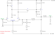
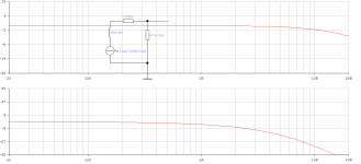
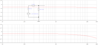
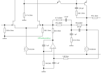
You can also read ( especially for hbtaudio - in English and freely!) 4 circuit advantages of my phono preamp topology with Passive cooling ultra low capacitance input 150k/25pF and Output TransAdmittance stage with ActiPassive constant loop gain RIAA EQ [ https://www.patreon.com/posts/90783025 ]. Attached is a simulation of my RIAA phonopreamp noise with input resistor R2 stepping 50...500 kOhms (RIAA equalized and IEC-A wtd output noise with 1K 500 mH cart @ input, Ku=49 dB @ 1 kHz).
LTspice (and indeed any spice simulator) actually does a very accurate job of plotting noise for any circuit over frequency, so no need for heavy calculations or spread sheets. A sim says the wideband input noise for a 500mH + 1000 Ohms cart terminated with 47k and 150pF total load capacitance is 3.1 uV
LTspice (and indeed any spice simulator) actually does a very accurate job of plotting noise for any circuit over frequency, so no need for heavy calculations or spread sheets.
Conversely, when you understand noise transformations, you don't need LTSpice. I personally spend so much time simulating at work that I try to avoid it as much as possible in my spare time.
Regarding noise transformations, the impact of resistor noise on the equivalent input noise can be found like this:
Part A shows a Thévenin equivalent of the cartridge comprising a voltage source with value vcartridge and an impedance Zcartridge. The only assumption I will make about Zcartridge is that it is nonzero. Whether it is resistive, inductive, capacitive, a bit of all and how it varies over frequency doesn't matter, as long as it is nonzero. The Thévenin equivalent of the cartridge is connected to a resistor R2 with some positive value that generates thermal noise and to some sort of amplifier.
Part B shows the very same circuit, but with R2 replaced with the Norton equivalent of a noisy resistor, consisting of a noiseless resistor and a noise current source inR2. The noise current source has a spectral density √(4kT/R2) (power spectral density 4kT/R2), although that isn't shown in the picture.
In part C, a Blakesley shift is used to split the current source into two fully correlated noise current sources, one across the voltage source and one across the cartridge impedance. The current they together inject into the node where the voltage source is connected to the impedance is inR2 - inR2 = 0, which is why this transformation is allowed.
However, it makes no difference whether the current source in parallel with the voltage source is there or not, as it has no effect on its voltage. We can therefore just as well remove the current source in parallel with the voltage source.
Now apply a Norton-Thévenin transformation to the cartridge impedance and the current source in parallel with it, and you end up with part D, which has a noise voltage inR2 Zcartridge directly in series with the Thévenin voltage of the cartridge. The spectral density is |Zcartridge| √(4kT/R2) (and the power spectral density is therefore |Zcartridge|2 4kT/R2). Note that this increases with decreasing R2.
If the amplifier is adjusted such that the transfer from the Thévenin voltage of the cartridge to the output stays essentially the same when R2 is changed, the noise at the amplifier output will also increase with decreasing R2.
Last edited:

47K/150pf and 150K/25pf loadings do not have the same frequency response, generator to output, so even with the same noise distribution over frequency cannot be compared directly. Is noise above audiblity (call it 20KHz for young people) to be considered? Below 20Hz? At some point noise is always weighted to audibility.
Should frequency (magnitude) response be first corrected to "flat"? This will be easy in near-future A/D-RIAA-D/A phono stages. That would be closer to a level playing field, but the issue of bandwidth limiting and ear weighting remains.
All good fortune,
Chris
Should frequency (magnitude) response be first corrected to "flat"? This will be easy in near-future A/D-RIAA-D/A phono stages. That would be closer to a level playing field, but the issue of bandwidth limiting and ear weighting remains.
All good fortune,
Chris
Marcel, let us focus on what we can measure electrically. You know as well as I do that as soon as you ask people what they hear, you get as many different answers as there are people participating.
Noise weightings are quite imperfect, especially A-weighting, but they correlate much better with what people hear than unweighted measurements.
You can measure A-weighted noise electrically, in fact I always do. Just insert an A-weighting filter before your true RMS meter, or digitize the signal and apply a digital A-weighting filter. ITU-R 468 noise is more complicated because besides a filter, it requires a special quasi-peak measurement. That also makes ITU-R 468 a pain in the rectal region for calculations and simulations, which is a pity, because it actually correlates best with what people hear.
Nick has claimed all sorts of fantastic figures for his preamp, all underpinned by acoustic/auditory perception weightings that I am afraid, as a first step to designing and building world-class phono preamps, do not move the dial forward. It would be nice to clear up the input noise discussion without muddling it with the science of a separate scientific domain.
In my experience, most well-designed phono preamps will be silent with the needle off the disc and the volume set to normal listening levels.
🙂 YMMV
In general, you cannot simultaneously optimize a MM amplifier for unweighted, A-weighted and ITU-R 468 weighted noise. Optimizing it for one of the three will usually lead to suboptimal results for the other two (although often not very suboptimal). That's why I prefer to optimize it for something that has a clear relation with audible noise.
More detail concerning the interrelationship of temperature and resistance:

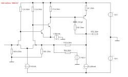
This is also always about the actual equalizer. That's why I'll pass on the basic schematic ..!
HBt.
Psst.
ISBN 978-3-642-54036-3
"Signal- u. Rauschanalyse mit Quellenverschiebung"
HBt.
Psst.
ISBN 978-3-642-54036-3
"Signal- u. Rauschanalyse mit Quellenverschiebung"
Attachments
Last edited:
And that is precisely the point of contention: in my opinion, it is secondary in the development (phase). This point only comes into play later - and is then hopefully (more) nothing more than a measurement.Noise weightings are quite imperfect, especially A-weighting, but they correlate much better with what people hear than unweighted measurements.
I can live with this statement very well. That's your point of view - and also a bit of your tool, your approach ...! Perfect. The only important thing is that you reach your goal. And I achieve that too, but I leave out any weighting.(...)
In general, you cannot simultaneously optimize a MM amplifier for unweighted, A-weighted and ITU-R 468 weighted noise. Optimizing it for one of the three will usually lead to suboptimal results for the other two (although often not very suboptimal). That's why I prefer to optimize it for something that has a clear relation with audible noise.
HBt.
This goal is also achieved incidentally if you have done everything right 😉
If the amplifier is adjusted such that the transfer from the Thévenin voltage of the cartridge to the output stays essentially the same when R2 is changed, the noise at the amplifier output will also increase with decreasing R2.
What is this manipulation Marcel?
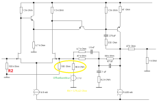
R2 determines the input resistance of the EQ amp. -no more and no less - 47kOhm vs. 150kOhm. Look at Nicks Input - jFet!
Now let's do the math:
NOISE = sqrt(4*1.3806*10^-23Ws/k*293k*20000 1/s *R2 V/A)
NOISE is proportional to R2, we consider this noise to be white. Now it is frequency-dependent amplified and thus colored according to the RIAA-blablabla.
If R2 increases, the resulting noise spectrum at the output of our amplifier increases in level.
Thats it.
Last edited:
Do you know "Die drei ???" ?And then you turn down the volume.
Unfortunately, I don't understand your statement Marcel.
150/ 151 = 0,9934 vs. 47/48 = 0,9792 is not a big deal; there is no need to turn up or down. We have already clarified the number with the "Blindwiderstand und Scheinwiderstand", haven't we?
😉
Ok, more signal-attenuation ... signal to noise ... What do you mean? The Disturbance of sensation?
Attachments
Last edited:
What is this manipulation Marcel?
R2 determines the input resistance of the EQ amp. -no more and no less - 47kOhm vs. 150kOhm. Look at Nicks Input - jFet!
Now let's do the math:
NOISE = sqrt(4*1.3806*10^-23Ws/k*293k*20000 1/s *R2 V/A)
Where on Earth did the cartridge impedance go?
NOISE is proportional to R2, we consider this noise to be white. Now it is frequency-dependent amplified and thus colored according to the RIAA-blablabla.
If R2 increases, the resulting noise spectrum at the output of our amplifier increases in level.
Thats it.
It is customary to look at equivalent input noise or equivalently at a fixed output level, because it is a measure for the effect on the signal-to-noise ratio. If you only care about the output noise and not about the signal, instead of 47 kohm or 150 kohm, you could much better use 0 ohm. It would be even better to simply switch off the circuitry, that also saves power. Better yet would be not to build the equipment at all, thereby saving all the energy and raw materials required for building the RIAA amplifier.
Assuming that you do want to have signal, want to have some volume level that suits you and want to have proper RIAA equalization, the transfer from the cartridge EMF to the output has to somehow be made more or less equal for both cases.
I write more or less, because Nick's scheme actually extends the high-frequency range. An extended high-frequency response may in fact lead to more integrated output noise, even though the equivalent input noise density is smaller. That could easily be fixed with a low-pass filter after the RIAA amplifier, although it would be stupid to do so.
Here is ( "Where on Earth did the cartridge impedance go?" ) now and for ever
Could we put the temination issue to one side now? And perhaps turn our attention back to the transducer.
Dear Marcel,
please don't keep trying to lead me up the garden path, please accept that there is no small, uneducated boy on the other side of the screen.
Where is the correct (contemporary) modeling of the pickup?
It's Christmas, Peace please,
HBt.
Attachments

Do whatever you like, I'm so fed up with the whole discussion that I will unwatch this thread.
Dear Marcel.
I am very sorry about that. But you were constantly squirming.
We should simply reflect on the whole background again after a few days' rest.
All the best,
HBt.
I am very sorry about that. But you were constantly squirming.
We should simply reflect on the whole background again after a few days' rest.
All the best,
HBt.
I write more or less, because Nick's scheme actually extends the high-frequency range. An extended high-frequency response may in fact lead to more integrated output noise, even though the equivalent input noise density is smaller. That could easily be fixed with a low-pass filter after the RIAA amplifier, although it would be stupid to do so.
That is interesting and was never the question - we all know the transfer functions by heart.
HBt.
- Home
- Source & Line
- Analogue Source
- Why 150 kOhms is better than 47 kOhms