Sorry, I've had another sleepless night. There's a war raging somewhere and Lower Saxony (Germany) is drowning due to climate change, it's been raining non-stop for weeks now.
So the know-it-all attitude is really only about an ideal source (which in reality does not exist) and the fact that in the case of two complex voltage dividers under consideration, the hypothetical SNR could be around 120dB and 123dB beyond the upper cut-off frequency of the storage medium.
That's all this nonsense is about?!

Nick Sukhov is of course right about the fundamental (complex) voltage divider behavior, which was not questioned.
So the know-it-all attitude is really only about an ideal source (which in reality does not exist) and the fact that in the case of two complex voltage dividers under consideration, the hypothetical SNR could be around 120dB and 123dB beyond the upper cut-off frequency of the storage medium.
That's all this nonsense is about?!
Nick Sukhov is of course right about the fundamental (complex) voltage divider behavior, which was not questioned.
Last edited:
Heavy bombardments in Kiev - Germany provides humanitarian and military aid in every respect, offers refugees safe accommodation and supplies. I am a German and I absolutely no longer react positively to hostility of any kind (no matter which direction it comes from). Of course I wish Nick Sukhov and his family all the best and peace with Russia soon, but I resent all unkindness and insinuations.
On the topic and the recommendation of Nick Sukhov, as I would like to understand it:
Nick wants to circumvent the common 2nd order low-pass behavior by letting the parasitic line capacities (total Cp) approach to zero. Now there is only a 1st order low pass whose cut-off frequency can be shifted significantly to the right by a higher impedance termination (the input resistance of the subsequent amplifier), electrically. In the overall sum of all individual aspects, he hopes for a slightly improved SNR, increasing (the improvment!) with the signal frequency, in the high frequency range of the audible spectrum. The MultiCap-Sim seems to clearly confirm the compromise with R2=re=150kOhm. Well, and Nick is right about that. The significance in practice is not really given, but theoretically Nick is right - and that's why he makes this recommendation.
Unfortunately, at least the first stage of the amplifier must now a be part of the sensor or integrated into the headshell. This is nothing new and is well known.
Nick apparently solves this hurdle by placing the entire MM Wonder EQ directly at the end of the tonearm and installing it in the frame. This is also nothing new and unfortunately does not completely eliminate Cp. But, regarding the marginal (and theoretical) SNR advantage in the high frequency range - Nick is absolutely right and so is Marcel. Everyone is right from this point of view and is telling the truth. But not with regard to noise. The SNR trick is a consequence of the low pass function alone.
Any apodictic commitment to 150k should be viewed with caution because not everyone uses the same MM system (and the simplified model only serves a specific purpose) and installs the equalizer into the headshell.
With this approach and its condition, we lose all flexibility.
The actual amplifier can be discussed in "ARTMASTERS" thread. I myself don't entirely agree with the equalization of the miracle, but that is a different topic (and above all not a point of contention).
Kind Regards,
HBt.
Last edited:
Dear Nikolai Yevgenjevich Sukhov,I am sorry but it seems hbtaudio do not know both Thevenin/Norton/Ohm .
I know all these names
and even more so what is behind this comment. That was a pretty nasty insinuation or already an attempt at manipulation. German engineers very rarely use names for basic relationships, they describe things in such a way that the function and its properties are immediately apparent. We say "voltage source, current source, ideal, real, network, voltage divider, equivalent two-pole, four-pole and talk about transformations, source shifts, superposition principle ..." now and then we also talk about theorems ...
And for our common forum future you can rest assured that your counterpart may even know a little better than you do, i.e. is at least on a par with you.
Some already call themselves great grandmasters - and sell their Gerber files of various basic circuits on a strange platform.
My contributions are free, I'm not a great grandmaster.
Let's just behave like two friends, with different countries of origin and languages.
Kind Regards,
HBt.
Absolutely correct and I have said nothing else all the time.Cartridge inpedance Z (typical 10...20 kOhms @ ITU-R weghting curve maximum or MarcelvdG`s 3...5 kHz noise balance point) is paralleled (ref. preamp input) with input resistor
This is also correct and cannot be otherwise, but why do you mention Harry Nyquist in passing? The majority of all DIYs are only intimidated by this - is Nyquist's stream of noise something special? No is just the normal thermal noise!(150 or 47) and Nyquist noise current flow to cartridge because of its much lower resistance than input res.
Now you throw Ohm's law into the mix - and all you really have is a node, a summation node.As in message #27, 47k noise current 83 pA according to Ohm produce on cartridge noise voltage Unoise=Inoise x Zcart=83 pA x 15k = 1.245 uV instead of 46 x 15k = 0.69 uV with 150k input resistor. 1.245 >>0.69, isnt it?
This is where the process of the simplest source-or model transformations comes into play.
In English theminology, which Germans can't understand because they logically call a banana a banana: Thévenin / Norton ... equivalent circuit.
Dear Nick,
if you would be so kind as to explain your calculation method with units step by step, others can find out what you have calculated correctly and what you may not have calculated correctly. Whether the system you have set up is also correct or valid.
Would you like to catch up on this?
I will then answer your own question as to whether your assertion and the calculation method are correct.
Thank you.
Last edited:
Let's break down your (own) two-liner
If we put the cart before the horse as you do, then the starting point is a series connection of two active resistors. R=R_wirk = R1 + R2. R1 is the ohmic wire resistance of the present generator coil. We should ignore excess-noise.
R=47kOhm + 1kOhm (according to your example) = 48kOhm.
Unoise = sqrt( 4*1.3806*10^-23J/k*293k*20*10^3 1/s*48*10^3V/A)
= 3.94µV
R=150kOhm + 1kOhm (according to your example) = 151kOhm.
Unoise = sqrt( 4*1.3806*10^-23J/k*293k*20*10^3 1/s*151*10^3V/A)
= 7µV
Expressed in currents:
3.94µV / 48kOhm = 82.1pA; 7µV / 151kOhm = 46.4pA.
And now the Sukhov miracle and the impedance of the electromechanical converter come into play:
You give us |Z| as 15kOhms and multiply by the (calculate noise) current to then claim this voltage is now the real noise source at the input of the amplifier with its infinitely large and completely noise-free input.
So, I wonder which of us (both) primary school students has not yet understood something properly.
(15kOhm)^2 = R1^2 +j^2*(2*PI*f*L1)^2
|Z|(4.764kHz) = 15kOhm with L1=0.5H and R1=1kOhm
Now your question is whether the product of (82.1*15) is not greater than (46.4*15) - of course it is greater.
And yet our class teacher would have to give you zero points, or does your "Zcart" represent an "Scheinwiderstand" of an equivalent voltage source (transformation of the complex potential divider), an internal frequency dependent resistor ...
Please clarify factually or provide two measurements that confirm your claims. Please do not make a video with a completely incomprehensible language for non-native speakers.
Thank you very much Nick,
HBt.
Psst.
Let's (both) sit down on the school desk again 😉.
Last edited:
Cartridge inpedance Z (typical 10...20 kOhms @ ITU-R weghting curve maximum or MarcelvdG`s 3...5 kHz noise balance point) (...)
Is this really your starting point of the story ???
(10+20) / 2 = 15.
If this is all about,
then any attempt to build bridges with you is unnecessary. I'm so sorry. We don't discuss on equal terms (currently you are silent anyway).
Bye,
HBt.
Last edited:
Now your question is whether the product of (82.1*15) is not greater than (46.4*15) - of course it is greater.
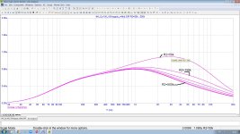
do you want me to multiply 82 by 15 = 1230, 46 by 15 = 690 and prove that 1230 > 690? 🤔 -please, if you can`t 😢 . Also attached is a simulation of my Cy-XXI phonopreamp noise density @ RIAA equalized and IEC-A wtd output with input resistor stepping from 50k "standard", to my passive cooling 150k and Marcel`s active cooling 500k. A 500 mH + 1k cart equivalent @ input attached.Please clarify factually or provide two measurements that confirm your claims.
Attachments
Please just explain what this nonsense here "to my passive cooling 150k" [N. Sukhov] means in plain language?
Apart from that, I'm not interested in your EQ, dear Nick - let it go.
Kind Regards,
HBt.
Apart from that, I'm not interested in your EQ, dear Nick - let it go.
Kind Regards,
HBt.
Last edited:
same as "The 47k load resistor is synthesized to reduce its current-noise contribution" in D.Self MM preamp [ https://www.diyaudio.com/community/threads/can-an-opamp-mm-phono-preamp-be-blamefree.401679/ ] and similar MarcelvdG`s topology, but without using any additional active elements like OPamp or transistors [ https://www.phaedrus-audio.com/electronic_cooling.htm ]. Are you really so "plain" and do not know basics ? 😢Please just explain what this nonsense here "to my passive cooling 150k" [N. Sukhov] means in plain language?
Last edited:
It's pure magic
A so-called passive component, an ohmic resistor, is operated under normal conditions - at ambient temperature.
You just have to give the child a name - "passive cooling".
Now I understand what you are saying, all your other components are also passive cooling - that's cool and very interesting.
Impressive!
Last edited:
Dear Nikolai Y. Sukhov,
so you can also say: nothing is cooled in your big throw. Convection is the maximum.
so you can also say: nothing is cooled in your big throw. Convection is the maximum.
Nick!
It is really clever of you' how skillfully you point out how much better your ordinary resistor is, with the value of 150000 ohms - in contrast to the active solutions of Douglas Self and Marcel van de Gevel, as well as (compared to) the 47000 ohm value of another ordinary resistor / itselfs / alone, without active support.
With your expertise, it is certainly easy for you to explain (in detail and with words and numbers only) the concept of electrically active cooling of an apparent 47000 ohm resistor. Would you do me this favor personally, since we are now very close buddies.
Thank you very much,
HBt.
Chapter 7, page 190 to 201, Douglas Self, "small signal audio design"
Let's compare the effect of an active, i.e. dynamically acting, 47k resistor with an equally activated 150k resistor.
Douglas Self himself doesn't like the phrase "active cooling" any more than I do; he speaks of a synthesis.
1M becomes 47k or even 150k.
Let's compare the effect of an active, i.e. dynamically acting, 47k resistor with an equally activated 150k resistor.
Douglas Self himself doesn't like the phrase "active cooling" any more than I do; he speaks of a synthesis.
1M becomes 47k or even 150k.
Attachments
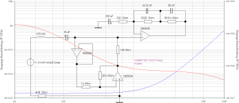

Now we compare your "passiv cooling"
150k (passiv) vs. 150k (activ) corresponds to a benefit of 0,186dB
150k (passiv) vs. 47k (passiv) corresponds to a benefit of 0,479dB
However, we are comparing apples with oranges here, as the resulting transfer functions H(jOmega) are not identical. But, the magic advantage alone is so powerful and so huge that ...
😱.
Bye, bye now
Attachments
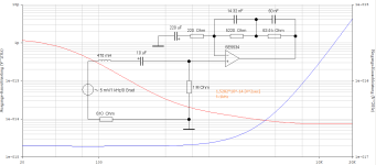
Let's compare one last time an apple called 47k with another apple called 150k, i.e. identical transfer functions of the 2nd order low-pass filter as a source before the EQ preamplifier.
And let's close the case for good. We register a really significant advantage of 5.2dB on the low impedance side.
The winner is:
Apple named 47k.
Nick my buddy!
I would very much appreciate it, and I'm sure the readers would too, if you would be honest for once and no longer throw sand in anyone's eyes.
In general,
an MM system should be terminated as specified by the manufacturer. Of course, you can also try to follow your suggestion and postulate it as universally valid - it's magic.
Will you accept this peace offering?
Attachments

Last edited:

Direct comparison 150k "passive cooling"© vs 47k "standard"
https://www.patreon.com/posts/direkt-tozhe-ne-96470558
and
https://www.patreon.com/posts/direkt-tozhe-ne-96470558
and
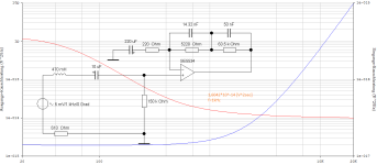
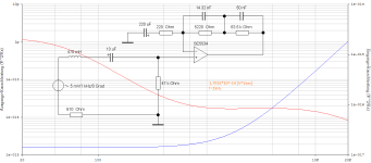
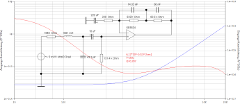
Pickup AT91:
L1=0.4H
R1=410Ohm
all values are assumed to be constant, which of course they are not.
A short calculator calculation results in
1)
Rp=47kOhm & Cp=250pF
Q=1,2
fog=16kHz
2)
Rp=150kOhm & Cp=25pF
Q=1,2
fog=50kHz !
Dear Nick,
So in the meantime you have unsoldered the 150k SMD resistor and soldered in a 47k and a 225pF capacitor instead - we'll take your word for it, to prove that 150kOhms linearly increase the cut-off frequency of a low-pass filter and at the same time increase the resulting SNR by an unbeatable 6dB absolute. You continue to insist on the advertising attribute "passive cooling by Sukhov", with which you only want to emphasize the uniqueness of a passive component, compared to Self's synthesis ...
Perhaps we should take a closer look at the topic of DSP in your new parallel advertising thread.
You are rightly asserting your position (defending your fortress) without anything constructive emerging.
This is a waste of time.
The chain looks like this:
Record, pickup, arm, drive, amplifier, EQ, amplifier, loudspeaker, ear - hearing.
Do it well, take care and no hard feelings
HBt.
Nobody denies the behavior of a low-pass filter - and I certainly don't. With that revelation, this thread should rest in peace and forever.
Thank you once again for your efforts Nick.
The analysis of the two raw data sets is very interesting, also your personal conclusion and so your recommendation is still the direct installation of the equalizer in the drive frame as well as a relatively high-impedance termination without any capacitive load on the pickup - as a general recommendation for all MM systems.
I can come to terms with that very well.
All the best,
HBt.
I suggest that we use your parallel thread for further discussions on this exciting topic:
https://www.diyaudio.com/community/...hono-preamp-confirmation.407764/#post-7567767
The number with the resistance value (and noise, SNR, signal level, transferfunction ...) has already been covered here.
Bye.
https://www.diyaudio.com/community/...hono-preamp-confirmation.407764/#post-7567767
The number with the resistance value (and noise, SNR, signal level, transferfunction ...) has already been covered here.
Bye.
- Home
- Source & Line
- Analogue Source
- Why 150 kOhms is better than 47 kOhms