
After Marcel feels misunderstood and Nick Sukhov offended, I can provide two curves that tip the scales back in favor of this party. Unfortunately, the tables can also be turned again, so for goodness sake I suggest thinking about two points: the evaluation / weighting and thus also the trasducer model used, as well as a comparative practical measurement under operating conditions.
The assertion that a higher resistance is fundamentally better because it produces less noise than a lower resistance is still wrong, as is the assertion that the actual amplifier with a higher input resistance produces less noise than one with a lower resistance.
Kind regards
HBt.
PS
Taken from the Aladdin simulation, the Sukhov SNR advantage is a full 0.331dB. It's basically nothing more than a trick.
Attachments
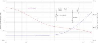
Now let's finally clear up the trick or the fairy tale: the typical TP2 behavior is used to distract from a non-constant transducer in a generalized way, to simplify inadmissibly! For a theoretically viable comparison, as a thought experiment, the frequency-dependent internal resistance of the signal source must also match our terminating resistor ..!
And then all is right with the world. What do we learn from this, the termination always consists of an Rp & Cp and should result in a filter quality between 0.707 and 1. A Bessel characteristic is also fine with me.
This comparison is valid and leads to the aforementioned SNR advantage of >3dB on the 47k side.
The apodictic assertion that a termination with 150kOhms always leads to better results is not honest. That's all there is to it, so for me the Sukhov topic is actually over. I have already said, that the generator model used cannot be correct. This model is only a simplification to make the correct termination more comprehensible.
Regards,
HBt.
Attachments

Last edited:
Measuring
is the ultimate solution to the dispute and the verification of the initial assertion of this thread.
is the ultimate solution to the dispute and the verification of the initial assertion of this thread.
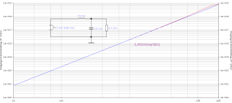
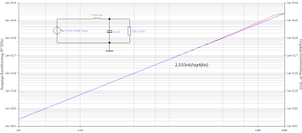
L1 is the cartridge equivalent, 500mH 500 Ohm. The first screenshot for C1=1nF, the second for C1=1pF. The "V(onoise)/gain" function takes care of the response changes and makes it clear that the real SNR at the input of the phono stage would not change with the load capacitance value (you could make it, say, 100nF in this simulation and the curves will not change). It also makes it clear that the SNR of the cartridge + load combination here is better with a 150K load resistor. There are other implications of the increased load resistance however these up to a certain degree can be addressed further down the signal chain.
Cheers
Alex
Cheers
Alex
Attachments

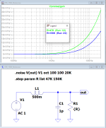
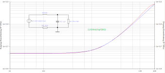
Years ago I did a SPICE noise analysis of the simple model of the phono cartridge and load with RIAA deemphasis. I played with the load to see the effect it had. The first thing you notice is that about half the noise is in the first decade, 20-200 Hz and the other half is in the remaining two decades, 200-20000 Hz. The load capacitor didn't have any noticeable effect on the noise. It might put a little resonant hump in the noise, but it was way down in amplitude.
Dear Alex,
your sim only reflects the typical lowpass behavier, with a constant value of L.
Compare with equal H(jOmega) - look now at the end of the chain.
Bye,
HBt.
your sim only reflects the typical lowpass behavier, with a constant value of L.
Compare with equal H(jOmega) - look now at the end of the chain.
Bye,
HBt.
I'll try again.
1) The SNR at the input does not depend on the load capacitance value. As soon as you correct the response, you'll get the same SNR for the same load resistor. That what my sim shows.
2) Please explain how you define "the correct termination of our cartridge".
Cheers
Alex
1) The SNR at the input does not depend on the load capacitance value. As soon as you correct the response, you'll get the same SNR for the same load resistor. That what my sim shows.
2) Please explain how you define "the correct termination of our cartridge".
Cheers
Alex
1) The SNR at the input does not depend on the load capacitance value.
SNR = signal / noise; (signal / n) / (noise / n) = SNR; SNR = SNR ! Actually, we wanted to talk about "the general noise", and nothing else - about the input resistance of a linear amplifier stage.
Do we really want to talk about filter theory, about analog 1st and 2nd order low-pass filters?As soon as you correct the response, you'll get the same SNR for the same load resistor. That what my sim shows.
Dear Alex,
that is (selectively) correct, but not the subject of the dispute. You basically just confirmed that the whole thread is about R2, I'll call him Rp now.
This resistance determines the input resistance of the Sukhov Wonder EQ.
If this request is also a question, then it is a very good question - because that is exactly what Sukhov is talking about.2) Please explain how you define "the correct termination of our cartridge".
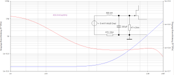
If we can imagine the pickup as an ideal voltage source whose internal resistance ("Blindwiderstand") increases linearly with the frequency, then a "reell", extremely high-impedance termination would be perfect - this means a very high input resistance of the subsequent amplifier, which we want to consider noise-free ourselves! There is now a first-order low-pass filter, which electrically determines our upper cut-off frequency of the signal source.
However, we (you) completely ignore the mechanical behavior of the pickup.
An example: Your pickup coil (we "like" to call it inductance, even if this term is not physically correct, because this term expresses a capability ...) If you assume that L1= [0.5 Vs/A; H] is constant, we can now set up the resulting transfer function with R2 and calculate an upper cut-off frequency according to the definition of the cut-off frequency.
with
150kOhm -> fog=47,75kHz
47 kOhm -> fog=14.96kHz
However, since there is a real coil and I have ignored the R1 wire ohmic resistance of the coil of perhaps 500 ohms, the -3dB point shifts slightly to the right.
If you would like to hear a crystal-clear sine wave of 200 kHz, for example, then the input resistance, i.e. R2, should be around 630 kOhm.
Is the sun slowly rising now?
Now to your question:
First of all you should be clear where the mechanical end lies - transmission behavior of the tactile system, the transducer, from an accelerated, delayed, movement to an electrical voltage (which is also nothing more than a potential difference -> thus represents a force).
Put the cart before the horse, or is it even the correct perspective?!
You would like to be able to reproduce and hear a fabulous sine wave (undistorted) with a frequency of 20kHz, then you define the upper limit of your transmission range. Let's just say (because this text is intended to help you understand the matter at hand) that the mechanical system, our transducer alone, must now be 10 times better than our defined frequency range according to the old rule of metrology. Then this inevitably results in an upper mechanical limit of 200kHz.
Let's now follow this rule and create a 2nd order low pass from our pickup, the converter.
Cp = 1/ (Omega^2 *L1) with Omega = 2*PI*20000 1/s
|Z| = sqrt(L1/ Cp)
If Rp = |Z| then Q=1.
I hope I was able to clarify what I wanted to express with a correct termination of the cartridge. It simply depends on the individual overall system consisting of drive, tonearm, cartridge, the electrical imagination and the desired upper limit frequency.
Bye,
HBt.
Psst.
NOISE is a separate and completely different topic.
Cp = 127pF
Rp = 62,83kOhm (-R1)
What is the mechanical limit of our storage medium and the mechanical system?
Last edited:
For a Butterwoth characteristic, R2 now approaches around 44kOhm; Alex!
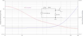
Compare A (1.194H; 53pF; 150kOhm) with B (0.374H; 167.3pF; 47kOhm) and set R1 to zero - I would be interested in this simulation comparison, then you compare almost identical H(jOmega), only the resulting (the frequency-dependent) internal resistance of our replacement signal source now differs.
Compare A (1.194H; 53pF; 150kOhm) with B (0.374H; 167.3pF; 47kOhm) and set R1 to zero - I would be interested in this simulation comparison, then you compare almost identical H(jOmega), only the resulting (the frequency-dependent) internal resistance of our replacement signal source now differs.
I myself' am not interested in apples and oranges comparisons, only in clarifications
Now with the resulting COIL-DC-Resistor:
A => 4,671nV/sqrt(Hz)
vs.
B => 2,614nV/sqrt(Hz)
Perhaps we can now slowly see the nonsensical thread and the question of what is less noisy as answered.
Of course, the lower impedance version of the same transfer function is less noisy than the higher impedance version.
Thank you!
Attachments

Last edited:
And you’ve got it wrong again. Somehow I have a feeling that you are missing some very basic stuff about how a simple circuit works. Let's forget an inductive cartridge. Let's see what happens with the SNR (and only the Signal to Noise Ratio really matters, not the absolute level of noise) with a simple resistive load. Let's take a 1V signal source with the internal resistance of 1kOm (self noise is ~4nV/rtHz, so SNR, for exaample, in 10kHz BW will be about 1V/0.4uV =2500000 or 128dB) and connect a load to it. For 1K load the noise will go down by 3dB (as the noise resistance now is 500 Ohm) however the signal voltage will go down by 6dB so the resulting SNR is 3dB worse at 125dB. WIth 10 Ohm load the noise voltage will go down 10 times or 20dB but the signal voltage will go down 100 times or 40dB, so the SNR worsens to 108dB. As you may see, without any sims, a resistive load makes SNR to suffer, and a lower resistance load makes it to suffer more.
Cheers
Alex
Cheers
Alex
"Ja und?"
And now? What is coming next?
There is no missing of knowledge on my side.
Sorry!
I am not wrong, I'm right and you know it.
"Prost"
HBt.
And now? What is coming next?
There is no missing of knowledge on my side.
Sorry!
I am not wrong, I'm right and you know it.
"Prost"
HBt.
Last edited:
Should I post for you the transferfunction for A vs. B? You have 46 years of audio experience against my 39 years. You must be right in your conclusion and false statements about me personaly, you must!
|H_A| is the same as |H_B|.
Sunrising now?
Greetings,
HBt.
PS
Wow, Jan D. like your impute ...
|H_A| is the same as |H_B|.
Sunrising now?
Greetings,
HBt.
PS
Wow, Jan D. like your impute ...
Last edited:
If you don't know what to do next, you have to defame and even insult your opponent - that's the law.And you’ve got it wrong again. Somehow I have a feeling that you are missing some very basic stuff about how a simple circuit works.
Agreed Alex, let's forget any dynamic consideration, i.e. +jX and -jX.Let's forget an inductive cartridge.
Ok,Let's see what happens with the SNR (and only the Signal to Noise Ratio really matters, not the absolute level of noise) with a simple resistive load. Let's take a 1V signal source with the internal resistance of 1kOm (self noise is ~4nV/rtHz, so SNR, for exaample, in 10kHz BW will be about 1V/0.4uV =2500000 or 128dB) and connect a load to it. For 1K load the noise will go down by 3dB (as the noise resistance now is 500 Ohm) however the signal voltage will go down by 6dB so the resulting SNR is 3dB worse at 125dB. WIth 10 Ohm load the noise voltage will go down 10 times or 20dB but the signal voltage will go down 100 times or 40dB, so the SNR worsens to 108dB. As you may see, without any sims, a resistive load makes SNR to suffer, and a lower resistance load makes it to suffer more.
I can do that too 😉. So let's consider a series connection of two ohmic resistors, the classic voltage divider.
"Zum Wohl Alex",Cheers
Alex
HBt.
Attachments
Sorry, I forget your very simple try ...
We spin in circles like a humming top!
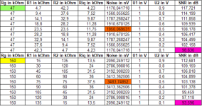
Rg in kOhm | R1 in kOhm | R2 in kOhm | Riq in kOhm | Noise in nV | U1 in V | U2 in V | SNR in dB |
48 | 1 | 47 | 0,9791666667 | 562,936584 | 1 | 0,9791666667 | 124,808 |
| | | | | | | |
Rg in kOhm | R1 in kOhm | R2 in kOhm | Riq in kOhm | Noise in nV | U1 in V | U2 in V | SNR in dB |
151 | 1 | 150 | 0,9933774834 | 567,006868 | 1 | 0,9933774834 | 124,871 |
| | | | | | | |
We spin in circles like a humming top!
I look to the future, because the following objection from the other side is about to come:
U2 = 1/sqrt( (1+R1/R2)^2 + (Omega*L1/R2)^2)
U1 = 1V
And then the top keeps spinning, but a cheeky boy suddenly throws a ball ..!
U2 = 1/sqrt( (1+R1/R2)^2 + (Omega*L1/R2)^2)
U1 = 1V
And then the top keeps spinning, but a cheeky boy suddenly throws a ball ..!
I'm also getting fed up.
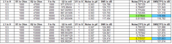
Finally, a spreadsheet calculation, the resulting internal resistance was not used to calculate the measured resulting noise and SNR.
I apologize for any mistakes, they are due to my dwindling attention - I just don't feel any energy left to score a point.
An attentive reader will recognize the relevant problems and the fundamental error in the mental exercise - and will also be able to understand and comprehend my statements.
I don't have the time or the inclination to summarize further
All is obvios.
Bye,
HBt.
Attachments
Last edited:
- Home
- Source & Line
- Analogue Source
- Why 150 kOhms is better than 47 kOhms