"Scheinwiderstände, (induktive & kapazitive) Blindwiderstände und Wirkwiderstände"
R means "Wirkwiderstand", i.e. resistance and the real component in ac-model-view
X means "Blindwiderstand", i.e. the imaginary component in ac-model-view
Z means "Scheinwiderstand", i.e. the impedance - |Z|=sqrt(R^2+X^2)
Marcel,
you say: that only R or 1/R = G is the parameter for noise calculations in this case, right? Nothing can change the situation, right?
Please answer only for clarification.
Thanks a lot,
HBt.
Yes, as long as you are referring to a thing without any power source. Thermal noise can only be generated by something that can also dissipate power.

That is the way I understand this. Assume an LC parallel circuit with a resonant impedance of 100kOhm. This 100 kohm is the real (dissipative) part of the impedance, parallel to the lossless C and lossless L. And the noise densitiy is given by thermal noise of 100kOhm - but only on the resonant peak. Besides this noise density drops according to the decreasing impedance. Thus you have a noise peak at resonant frequency, that will decrease with dampening of the resonant tank. This makes understanding of the RIAA-noise more complicated.
Another plot, this time with 50k vs 200k for simplicity and without capacitor.
The individual contributions of the resistors to the total output noise reveal the inner details.

The individual contributions of the resistors to the total output noise reveal the inner details.
- At low frequencies the total noise is strictly following the R1//R2 circuit equivalent. The 50k version thus produces a tiny bit less noise than 200k.
- There is a point at 2.3kHz (50k) and 4.5kHz (200k) where cart and load resistors contribute equal amounts.
- Above that point, R2 dominates and 200k gives lower noise (only 2/3rd of 50k version noise @10kHz). This region is the reason why one could say "150k is better".
- At 30kHz and beyond, though, 50k gives lower noise as the cart R's shorting effect is now becoming fully isolated by the inductance and accordingly its noise contribution goes to zero.
- At high frequencies the 200k load produces two times the noise vs 47k as expected.
At low frequencies, the amplifier would have to have a bit more gain with 47 kohm than with 150 kohm to play back the record equally loudly. When you correct for that, the noise is also higher with 47 kohm at low frequencies.
I am sorry but it seems hbtaudio do not know both Thevenin/Norton/Ohm . Cartridge inpedance Z (typical 10...20 kOhms @ ITU-R weghting curve maximum or MarcelvdG`s 3...5 kHz noise balance point) is paralleled (ref. preamp input) with input resistor (150 or 47) and Nyquist noise current flow to cartridge because of its much lower resistance than input res. As in message #27, 47k noise current 83 pA according to Ohm produce on cartridge noise voltage Unoise=Inoise x Zcart=83 pA x 15k = 1.245 uV instead of 46 x 15k = 0.69 uV with 150k input resistor. 1.245 >>0.69, isnt it?
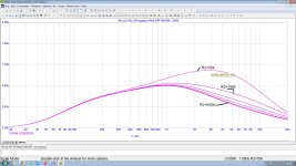
You can also read ( especially for hbtaudio - in English and freely!) 4 circuit advantages of my phono preamp topology with Passive cooling ultra low capacitance input 150k/25pF and Output TransAdmittance stage with ActiPassive constant loop gain RIAA EQ [ https://www.patreon.com/posts/90783025 ]. Attached is a simulation of my RIAA phonopreamp noise with input resistor R2 stepping 50...500 kOhms (RIAA equalized and IEC-A wtd output noise with 1K 500 mH cart @ input, Ku=49 dB @ 1 kHz).
You can also read ( especially for hbtaudio - in English and freely!) 4 circuit advantages of my phono preamp topology with Passive cooling ultra low capacitance input 150k/25pF and Output TransAdmittance stage with ActiPassive constant loop gain RIAA EQ [ https://www.patreon.com/posts/90783025 ]. Attached is a simulation of my RIAA phonopreamp noise with input resistor R2 stepping 50...500 kOhms (RIAA equalized and IEC-A wtd output noise with 1K 500 mH cart @ input, Ku=49 dB @ 1 kHz).
Attachments
Last edited:
@MarcelvdG , OK but then for a fully normalized noise spectrum comparison (same final frequency response), we should also correct for the lower gain at higher frequencies with 47k because the pole shifted down. About a 1dB (10%) at 10kHz which increases the advantage for 150k.
when you keep in mind IEC-A or ITU-R weghtings and such a fact that freq band before 3 kHz is much less than that of after 3 kHz, you see such "a tiny bit" absolutely negligible. See my attach @ #46Another plot, this time with 50k vs 200k for simplicity and without capacitor.
The individual contributions of the resistors to the total output noise reveal the inner details.
- At low frequencies the total noise is strictly following the R1//R2 circuit equivalent. The 50k version thus produces a tiny bit less noise than 200k.
- [skipped]
Nonsens Nick, please read carefully my post and be more carefully with your assumptions.
HBt.
I know my stuff very well, this is for your personal information only - dont't do it again.
HBt.
I know my stuff very well, this is for your personal information only - dont't do it again.
Is there no Source? What is then the transducer for you? Please give us a correct modulation of these source. Not the stupid L plus R as riq of an ideal voltage source.Yes, as long as you are referring to a thing without any power source. Thermal noise can only be generated by something that can also dissipate power.
In the correct view please lay beside all weigthings, and the RIAA-Curve ... only the transducer and Input are of our interest.
Don't twist again.
Thank you very much,
HBt.
Why? Seems to be reaching. The topic is interesting because it's appropriate to real, actual use (for DIY), which is both RIAA'd and ear weighted. Shifting noise out of band is the basis of modern audio storage schemes.please lay beside all weigthings, and the RIAA-Curve ... only the transducer and Input are of our interest.
All good fortune,
Chris
In attach an interesting article from 1981, nr. 1 of Audioreview.
It is in italian, sorry, but very complete
The Title is :
Surprise, the head has more noise than preamp.
Then a theory and test with also the help of HP 85!!!
The people who created this tech articles were very smart; I know them very well
It is in italian, sorry, but very complete
The Title is :
Surprise, the head has more noise than preamp.
Then a theory and test with also the help of HP 85!!!
The people who created this tech articles were very smart; I know them very well
Attachments
As soon as you play a record, there will be more noise coming out of the cartridge than just thermal noise, namely thermal noise and converted record surface noise.
As long as you don't play a record, there is nothing supplying power, and the cartridge can only generate thermal noise. That thermal noise depends on temperature and on the real part of the cartridge impedance or admittance.
A thing with two terminals in thermal equilibrium with its surroundings (that is, with no power source) cannot produce more or less noise than fits the real part of its impedance (or admittance), as otherwise you would have a free heat pump when you tune out the reactance (or susceptance) and connect it to an ordinary resistor. The thing would then supply more or less noise power to the resistor than it gets back from the resistor, which would violate the second law of thermodynamics.
Last edited:
Exactly Marcel,
and now we are back to two resistors and these are dynamically connected in parallel.
1||47 is slightly smaller than 1||150. We all know that the equivalent resistance is now rushing thermally for us and we can use exactly this value in our well-known calculation formula. Well, and now let's all be honest, 1||47 is minimally less (voltage) noisy; let's leave exess-noise aside, please.
So now it's time for the practical test - the generator finally does what it's supposed to do and we'll stop beating about the bush.
Let's deal with the operating case, shall we?
Regards,
HBt.
Why? Seems to be reaching. The topic is interesting because it's appropriate to real, actual use (for DIY), which is both RIAA'd and ear weighted. Shifting noise out of band is the basis of modern audio storage schemes.
All good fortune,
Chris
Quite right Chris,
however, for general understanding and plausibility checks of appodictic assertions - which are not exactly universally valid - one must use clear reductions and focusing. If necessary, a false statement must be labeled as such. Let us always consider the context.
Merry Christmas now,
HBt.
Hah. Not really. I didn't think about much at all. I just tried when I saw this, out of curiosity, because it's easy to try when the model is already sitting there.did you think it so?
Though, my result depends on model accuracy which ahas yet to be proven.Though, I have been tweaking it for a while now trying to make it as real as I can.
If it is true the total noise energy cannot be changed but maybe instead can only be manipulated in and out of the audible band, it still seems like it may be a handy tool to understand how to use.
You math gurus tell me what you decide.
Thank you waltube for the PDF
My Italian sucks but I added it to my reference files
Good stuff as you said
My Italian sucks but I added it to my reference files
Good stuff as you said
I do wish everyone would drop the ‘A’ weightings etc because those specifically relate to how the ear-brain system interprets an acoustic signal wrt frequency i.a.o things. 86 dBA means nothing to me. It’s the stuff audiologists and acousticians think about, not electrical engineers.
The RIAA response weighting however must be included because it is shaping the electrical signal from the transducer.
In other words, separate the acoustic and electrical domains and for now focus just on the electrical performance. We then have a level playing field.
🙂
The RIAA response weighting however must be included because it is shaping the electrical signal from the transducer.
In other words, separate the acoustic and electrical domains and for now focus just on the electrical performance. We then have a level playing field.
🙂
I wish people would stop doing audio noise measurements without A- or ITU-R 468 weighting. Unweighted measurements have very little relation to the amount of noise you actually hear.
In the case of phono preamplifiers with bipolar transistor or valve input stages, they lead to different noise optima than weighted measurements. That is, you get a higher audible noise floor than needed due to an illogical optimization criterion. Fortunately the difference is small for bipolar transistor input stages, but still.
In the case of phono preamplifiers with bipolar transistor or valve input stages, they lead to different noise optima than weighted measurements. That is, you get a higher audible noise floor than needed due to an illogical optimization criterion. Fortunately the difference is small for bipolar transistor input stages, but still.
Marcel, let us focus on what we can measure electrically. You know as well as I do that as soon as you ask people what they hear, you get as many different answers as there are people participating.
Nick has claimed all sorts of fantastic figures for his preamp, all underpinned by acoustic/auditory perception weightings that I am afraid, as a first step to designing and building world-class phono preamps, do not move the dial forward. It would be nice to clear up the input noise discussion without muddling it with the science of a separate scientific domain.
In my experience, most well-designed phono preamps will be silent with the needle off the disc and the volume set to normal listening levels.
🙂 YMMV
- Home
- Source & Line
- Analogue Source
- Why 150 kOhms is better than 47 kOhms