Sorry @andyjevans , don't mean to hijack your thread.>>
No problem - if there's anything useful to you here. We've covered a lot of ground.
No problem - if there's anything useful to you here. We've covered a lot of ground.
@andyjevans: If woofer control turns out to be a problem with your SET amp, you could always give CFB a try just by inserting the OP secondary between the output tube´s cathode resistor and ground (with correct polarity of course). EL12N seems to have quite high amplification factor and could possibly benefit from a little bit of local feedback. CFB from an 8 ohm winding doesn't provide a lot of feedback, 2-3dB or so depending on the output tube mu, but it usually helps to tighten things up a bit at the expense of moving one wire connection and a slightly lower gain.
Interesting idea, Fuling. The thing is that I already like the sound from my Mission 761 speakers, which are sealed in 10.5 litres or so, with my SE amp. So I already have a working blueprint. The EL12n in triode do indeed have a gain of around 18 but they seem to work OK into a sealed box. I just want to improve on it, that's the whole point of better units in an aluminium enclosure. I was a bit romantically influenced by the Magico A1, which is a sealed box of around 15 litres with a 6.5" mid-bass. That was the kind of thing I was aiming for all along. I just thought I could do it much cheaper. I mean, not the same level of excellence, but better than an all-wood cabinet. Less coloration so a cleaner bass amongst other things. That's my "true confession". I wanted a cheap Magico!

I see. Looks like an interesting speaker!
Sealed enclosures are, as far as I know, less picky about output impedance than bass reflex boxes. Aperiodic boxes are better still with their smoother impedance.
With a mu of 18, EL12N would definitely be a candidate for CFB since it becomes more effective at higher mu. Perhaps even too effective, but worth a try. CFB is kind of known for helping with woofer control without the sonic penalties of global NFB, but it doesn't work well with all transformers so it must be tested in situ.
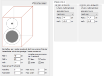
To the OP: try Boxsim. I fiddled around with an 8" and a 1" in the WG148 waveguide, in a 10x16x12" enclosure. The app is quite reliable and this design will almost certainly sound pretty good. Not that you'd have to build it. But it's a good way to learn designing
Attachments

You can flatten out the FR, but the dampening won't improve. Its not possible to improve dampening with just an FR correction from the front side line level of the amp. If you want to improve dampening, you must use some sort of feedback loop from the output to the input.Yes you can that's exactly what the Linkwitz Transform is for.
Damping perhaps but this is not how loudspeakers work for the majority of the time. The majority of the time they are being driven by a signal even right down to zero amplitude. If there's ringing in an underdamped loudspeaker system then all you need to do is drive that ringing with the opposite signal and it completely goes away. Thus if you use a filter that drives an underdamped system, with a precisely tuned signal that electrically counteracts the oscillation, then it's as if it's not there.
The Linkwitz Transform does precisely this. That's exactly what the point of it is. To equalise the system so that its end effective Q is indistinguishable from the real thing.
Transients always seem to be misunderstood to where a signal is applied and then the loudspeaker system is left to decay under its own devices. This is not the case. A transient in music is electrically driven from the peak of the signal right down to the end of when it's decayed. At no point was the loudspeaker system left to decay on its own. Yes the systems own acoustic properties are added to the driven signal and if unequalised that high Q system will be peaky. But if you apply a LT to the system it modifies that drive signal to completely counteract the systems inherent, high Q, response to whatever you want it to be.
@5th element I understand what you're saying. It makes sense you could in theory drive the ringing out via predicted negative corrected drive signal. It does require all of the corrections be defined in the algorithm itself. That means any stored energy problems in the cone itself can't be accounted for, since they originate in the mechanical radiating surface and not at the voice coil drive signal. Its also a digital only solution, which for some of us analog lovers isn't an option. I can see how this also would take alot of current to correct in the LF region.
Sim for the Troels Seas 18RLY 24 liter
Quick stretchy doo to see sim vs the posted
data for comparison. Load matches, good
enough to see freq response/filter
and 38 ohm peak at crossover.


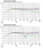
So now can see data without weasel merges below 450 Hz
just look at full space and off axis.


Quick stretchy doo to see sim vs the posted
data for comparison. Load matches, good
enough to see freq response/filter
and 38 ohm peak at crossover.
So now can see data without weasel merges below 450 Hz
just look at full space and off axis.
I think 5th-element describes what is called a feed forward compensation. Including a correction signal, that previously has been done for the speaker chassis, into the music signal. So you know what your speaker will do wrong and compensate for it before it happens.
It has been done, but did not find it's way into audio as far as I know. Probaply because it needs to be perfectly matched to the individual speaker. In the end other systems worked better with less problems.
It has been done, but did not find it's way into audio as far as I know. Probaply because it needs to be perfectly matched to the individual speaker. In the end other systems worked better with less problems.
Stored energy problems in the cone are not what we're discussing here. We're talking about changing the effective Q of a sealed box woofer with a Linkwitz Transform circuit. This is well below any frequency at which your typical 6.5" woofer will exhibit cone based resonances.@5th element I understand what you're saying. It makes sense you could in theory drive the ringing out via predicted negative corrected drive signal. It does require all of the corrections be defined in the algorithm itself. That means any stored energy problems in the cone itself can't be accounted for, since they originate in the mechanical radiating surface and not at the voice coil drive signal. Its also a digital only solution, which for some of us analog lovers isn't an option. I can see how this also would take alot of current to correct in the LF region.
I am not. Just your typical LT.I think 5th-element describes what is called a feed forward compensation. Including a correction signal, that previously has been done for the speaker chassis, into the music signal. So you know what your speaker will do wrong and compensate for it before it happens.
It has been done, but did not find it's way into audio as far as I know. Probaply because it needs to be perfectly matched to the individual speaker. In the end other systems worked better with less problems.
I get it. Wasn't intending to divert subject. Just looking at the practicality of the whole thing. To me, driver resonances are more significant of a problem than LF correction, but i can see in theory transient corrections can be made on the front side if the algorithm is properly defined to do so. I dont think its practical to do this if going through the hassle of running a tube output stage.Stored energy problems in the cone are not what we're discussing here. We're talking about changing the effective Q of a sealed box woofer with a Linkwitz Transform circuit. This is well below any frequency at which your typical 6.5" woofer will exhibit cone based resonances.
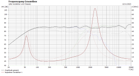
Better match for 8 ohm transformer...smoooth , fixed 40 ohm peak
sealed 24 liters , same baffle.


Original Troels Vented 24 liters impedance / load phase


can see the skinny baffle step at 500 / 600 Hz in full space.
possible to pull that out. but sensitivity be down to 82 dB
to actually be flat. Or add second woofer, or wider
baffle , or use typical slight bump on bass knob.
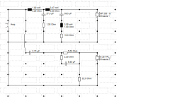
Revised Crossover using same small baffle as Troels above

even with baffle step taken out. The Troels Seas 6.5" technically hits 85 dB
but if the skinny baffle step was fixed better. It is actually be more like
82 dB.
Yours all good 85 dB across . Just need to fix that 65 ohm....peak at crossover.
Make it smooth for tuber and solid state.


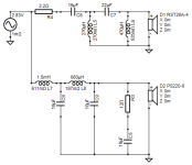
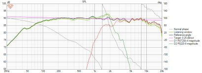
I did quick 8" 2 way with PS220_8 to try and get up to 90 dB
Smooth impedance. Large metal dome no waveguide.
Just large rear cavity tweet for low Fs. To bad no go for
Dayton stuff for OP.


sealed 24 liters , same baffle.
Original Troels Vented 24 liters impedance / load phase
can see the skinny baffle step at 500 / 600 Hz in full space.
possible to pull that out. but sensitivity be down to 82 dB
to actually be flat. Or add second woofer, or wider
baffle , or use typical slight bump on bass knob.
Revised Crossover using same small baffle as Troels above
Good way to go 8" 2 way, my sorta thing, Nice, Is actually flat across 85 dB.I fiddled around with an 8" and a 1" in the WG148 waveguide
even with baffle step taken out. The Troels Seas 6.5" technically hits 85 dB
but if the skinny baffle step was fixed better. It is actually be more like
82 dB.
Yours all good 85 dB across . Just need to fix that 65 ohm....peak at crossover.
Make it smooth for tuber and solid state.
I did quick 8" 2 way with PS220_8 to try and get up to 90 dB
Smooth impedance. Large metal dome no waveguide.
Just large rear cavity tweet for low Fs. To bad no go for
Dayton stuff for OP.
I think Siegfried and all his findings are disappearing from our collective memory too fast 😕 but this is pretty basic filter and network theory, very analog -ish.
But true, it requires some basic active circuits to work, thanks to the DSP era we tend to forget that too.
But true, it requires some basic active circuits to work, thanks to the DSP era we tend to forget that too.
Agreed, but I leave that -adding one or two LCR circuits- to the OP when he has fired his copy of Boxsim (or VCad).Yours all good 85 dB across . Just need to fix that 65 ohm....peak at crossover.
Make it smooth for tuber and solid state.
View attachment 1234426
This is true, but the way the world goes. Linkwitz theorie is quite complicated in analogue practice. Digital reality has made it historic.
We can compare it to carburetors an engines, they have been replaced by electronic injection systems. Sure, not so impressive, but better in any aspect.
Now, as we build the nearly perfect gasoline engine, all this is dumped for an even older tech: The electric motor. Highly skilled engine specialists are replaced by a few idiots importing universal electric hub motors from China.
It does not care what is better or cleaner. Cheaper to build and better suited for the majority of consumers is all that counts.
Maybe we have gone a bit OT? May we remember the 4 Watt valve amp?
I had a close look at the previous simulations. Not one of them would make Andy happy. They just pronounce the shortcoming of his weak amp with high output impedance. The Visaton simulation has a grave mistake in the tweeter x-over, that will net high distortion (6dB).
- Home
- Loudspeakers
- Multi-Way
- Which 6.5" mid-bass for a sealed box?