Thanks Reinout,
I thought, that a mono breadboard can be enough for sound quality evaluation. It is not. You should have both channels. Even after building the amp I had changed configuration probably 10 times, different drivers, different caps, different number of chokes, so it is a good practice to have some additional windings on your power transformers and additional space for tubes and iron. My first version has the input step-up transformers which worked fine, but it didn't have the dynamics of the active stage, so I had to punch additional holes in a chassis. I had 5V windings for AC heating, but to lower the hum I had to switched to DC and the heater voltage was to low, so voltage doubler with a voltage stabilizer was a must. The same 5V windings I used to get 6.3V with a voltage doubler. This is never ending story....there is always a place for upgrades. My monoblocks are a bit more handy than your amp having about 40kg each. I have them on a trolleys, so I move them a few meters and put them on a chair and turn them on a side. I couldn't imagine them to be a closed design with no access to the inside.
What is a sound? Very good, but I noticed, that the sound is mostly determined by a drivers. GM70 itself is very neutral and transparent sounding tube. What you use in a front is what you get at the output.
regards
Maciej
Attachments
Definitely!!! I was so dissapointed not to be able to go to the European Triode Festival and VSAC 2003..Bas....i signed up....see you there ?!)
This time I have no excuses...since it will only cost me 15 Euros (Allready Paid) and some fuel ofcourse...
Room for modifications
Hi Maciej,
of course you need 2 channels to get a proper sound. But what i mean to say is that my girlfriend does accept already a lot of my strange audio-hobby. She "only" asks to make the result/finished part living room-acceptable. So NO lose wires (which you don't want anyway with kV+ voltages.....). That is in my opinion a more than normal question.
In order to do so: first make the project working. Then make a nice casing WITH room for a lot of changes.
Changes in the meaning of resistors/capacitors as drop-in-replacements are never a problem. There is always room for them. Changes in a complete different set-up or really different schematic which leads to a totally different lay-out of the components:.......you left your breadboard stage too early. Am i already finished with the amps: of course not. It's part of the hobby to "search the holy grail of tube-audio" (if that already exists). But after some time i have chosen for a certain configuration + lay-out. Now that's my amplifier and i'm going to optimise that as long as it takes.
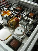
An example of optimalisation: all my powersupply transformers are winded with correction taps. They let you vary the primary windings +5% / +10%. So even with a number of different secondary taps (and i don't use many secondaries for almost every possible powerline does have it's own dedicated transformer) you can chage that within limits in order to find the optimum sweetpoint.
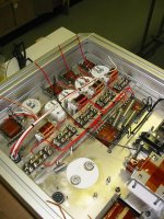
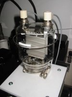
At the attached picture you can see a part of the powersupply. Lots of room (to be honest: i already changed a couple of transformers) and the profiles i use for the casing have a nice feature: you can bolt anything to it without tapping holes ! See also my next mail to Bas Horneman.
With regards,
Reinout
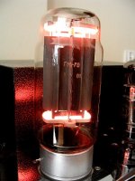
(nice picture of the GM70 !)
Hi Maciej,
of course you need 2 channels to get a proper sound. But what i mean to say is that my girlfriend does accept already a lot of my strange audio-hobby. She "only" asks to make the result/finished part living room-acceptable. So NO lose wires (which you don't want anyway with kV+ voltages.....). That is in my opinion a more than normal question.
In order to do so: first make the project working. Then make a nice casing WITH room for a lot of changes.
Changes in the meaning of resistors/capacitors as drop-in-replacements are never a problem. There is always room for them. Changes in a complete different set-up or really different schematic which leads to a totally different lay-out of the components:.......you left your breadboard stage too early. Am i already finished with the amps: of course not. It's part of the hobby to "search the holy grail of tube-audio" (if that already exists). But after some time i have chosen for a certain configuration + lay-out. Now that's my amplifier and i'm going to optimise that as long as it takes.
An example of optimalisation: all my powersupply transformers are winded with correction taps. They let you vary the primary windings +5% / +10%. So even with a number of different secondary taps (and i don't use many secondaries for almost every possible powerline does have it's own dedicated transformer) you can chage that within limits in order to find the optimum sweetpoint.
At the attached picture you can see a part of the powersupply. Lots of room (to be honest: i already changed a couple of transformers) and the profiles i use for the casing have a nice feature: you can bolt anything to it without tapping holes ! See also my next mail to Bas Horneman.
With regards,
Reinout
(nice picture of the GM70 !)
Attachments
Profiles
Bas,
looking forward to meet you. I already wrote to the organisation of the Dutch DIY Audio Day and explained that i would bring my 6C45-based phono stage and my 6SN7-based headphoneamp. Sorry......i do not bring the 833-amps for obvious reasons. But i will bring with me a couple of the ITEM-pofiles i told you about. See also the picture: the rectangular profile in the middle/back is the profile i used as side-pieces for the amps. The top- and bottomplates can be very easy bolted to it. In the slots you can slide a wedge-shape nut in which a M5/M6/M8 thread is already tapped.
There are also 2 slots on the inside of the profile....so you can bolt extra's INSIDE the amplifier without having to drill again in the top- or bottomplates. This gives me the flexibility to change my amp without doing the drilling part all over again (see also the post to Maciej).
See you the 17th,
Reinout
Attachments

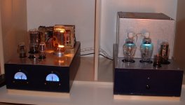
my amp
Hi Reinout,
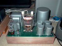
here's a picture of one channel of my gm70 amps.
Ofcourse they can't really compare to the polished look of chrome/steel like yours or Maciej's, but not that bad.
casings are mdf, tubesockets are placed on pieces of pcb, under the wooden topplate, and on top of the mdf plate there is a thin plate of aluminium to cover all screwholes.
the transformers on the ampchassis are still waiting for a coverbox like on the powersupply. But that'll have to wait.
I'm busy on a "small" pre-amp right now.
Filip.
Hi Reinout,
here's a picture of one channel of my gm70 amps.
Ofcourse they can't really compare to the polished look of chrome/steel like yours or Maciej's, but not that bad.
casings are mdf, tubesockets are placed on pieces of pcb, under the wooden topplate, and on top of the mdf plate there is a thin plate of aluminium to cover all screwholes.
the transformers on the ampchassis are still waiting for a coverbox like on the powersupply. But that'll have to wait.
I'm busy on a "small" pre-amp right now.
Filip.
Attachments
Hi Filip!
Amps are beautiful!
Can you tell me more about it's configuration, drivers, etc. any schematics?
How do you like the sound?
regards
Maciej
Amps are beautiful!
Can you tell me more about it's configuration, drivers, etc. any schematics?
How do you like the sound?
regards
Maciej
Hi Maciej,
the powersupply contains a 1000V supply (with mercury vapor 866's, nice lightshow in the evening), a 400v supply with 83 or equivalent (5z3 I think), and a 6x5gt for a bias supply.
and of course a bunch of filament supplys.
the inputstage for the amp is a 76 with a ccs as load, cap coupled to a 300b. the 300b is choke loaded, fixed bias. The bias suply goes through the purple glowing od3... there is a check for this voltage, if there is no bias voltage, the ht won't start and the amp shuts down completely.
the gm70 stage is auto bias with a big resistor. and 300b to gm70 is direct coupled. To allow this I stacked the whole gm70 stage on top of the lower powersupply.
The advantage of this way is that it is completely stable, if the 300b is not in it's socket, the gm70 is still completely biased.
Disadvantage is that I had to put in a mosfet regulator for the 300b voltage as to get it very solid. otherwise I would have more hum than in normal coupling, and gm70 voltage referenced to ground.
Sound? for direct reference I only have my solid state marantz receiver (sr7000), which is already very good.
But I prefer the sound of the gm70.
It gives a nicer sound to the bass, and it feels more spatial than the marantz. (when I connected the receiver back to the speakers my wife said "what did you do to the bass? it's gone. Put it back." 🙂 )
I haven't heard that many tube amps to compare with, so I guess my tuning will be too "solid state" for a lot of people.
My intend in the amps, is to keep it simple, without feedback, and make it so as to have as little distortion as possible, as much bandwidth as poss. and as silent as possible.
The gm70 and 300b are excellent tubes in that respect, very easy to get good sounding results.
I feel that only after that you can start putting in "boutique" parts, like special caps/resistors.
I added a switch to dial in some feedback (about 7db I think), but I never use it. I prefer without the feedback.
Filip.
"I haven't heard that many tube amps to compare with, so I guess my tuning will be too "solid state" for a lot of people"
thanks Filip,
I think my amp is also a bit SS like. It is very detailed, very clean, sometimes a bit hard, but I prefare it to TYPICAL tube sound, fat, warm, slow. I experiment with different parts, sometimes very expensive, like BG WKZ caps , amorhphous core transformers etc.
The better parts I use, the more SS sound of the amp I get🙂
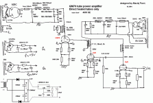
If you have the 1000V on the GM70 anode and you have 300B driver direct coupled to GM70, you should have something like 600V on a GM70 anode/cathode only (about 350V at 300B anode and about 50V for GM70 gbias/grid).
regards
Maciej
thanks Filip,
I think my amp is also a bit SS like. It is very detailed, very clean, sometimes a bit hard, but I prefare it to TYPICAL tube sound, fat, warm, slow. I experiment with different parts, sometimes very expensive, like BG WKZ caps , amorhphous core transformers etc.
The better parts I use, the more SS sound of the amp I get🙂
If you have the 1000V on the GM70 anode and you have 300B driver direct coupled to GM70, you should have something like 600V on a GM70 anode/cathode only (about 350V at 300B anode and about 50V for GM70 gbias/grid).
regards
Maciej
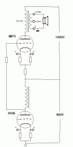
Hi Maciej,
The 1000v is stacked on top of the 350v supply.
I attached a representation to show what I mean.
This way the 300b and gm70 are direct coupled, but I can't try out fixed bias on the gm70, and instead of a coupling cap, there is a cap across the cathode bias resistor. <<sigh>> there is always a compromise somewhere.<</sigh>>
Ofcourse with an interstage I could also go A2 and use fixed bias...
You described exactly how I want my amp to sound/evolve. Not the fat/mushy sound that is typical. (that and a big 50Hz hum is what most people think of when you tell them you build tube amps.)
There are still a lot of details in tube sound otherwise than that I believe.
regards,
Filip.
MaciekP said:"I haven't heard that many tube amps to compare with, so I guess my tuning will be too "solid state" for a lot of people"
thanks Filip,
I think my amp is also a bit SS like. It is very detailed, very clean, sometimes a bit hard, but I prefare it to TYPICAL tube sound, fat, warm, slow. I experiment with different parts, sometimes very expensive, like BG WKZ caps , amorhphous core transformers etc.
The better parts I use, the more SS sound of the amp I get🙂
If you have the 1000V on the GM70 anode and you have 300B driver direct coupled to GM70, you should have something like 600V on a GM70 anode/cathode only (about 350V at 300B anode and about 50V for GM70 gbias/grid).
regards
Maciej
Attachments
rectifiers
Helllo Filip,
very nice amp, congratulations ! The GM70 looks very good (as Maciej's).
I noticed that you use mercury-rectifiers. Played also with that idea.......but skipped that in favour of hexfred's. My daily work is involved with radars/lasers and there a lot of hexfred's are used because of there very very low noise figure.
Besides that: i wanted all my needed powerlines to be completely independent of each other. Doing that with tube-rectification than the already quite large powersupply would become really unmanageble.
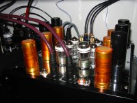
The last few years there is been booked quite some progress on SS-rectification. Not only hexfred's, but there are more variants which have great audio-potential. But i'm used working with the hexfred's......so the choice was simple. I found IXYS DSEP 2x61-12A which have 2 seperate diodes in one package. So it was vey easy to make "bridge modules" (see picture). And with their 60 Ampere / 1200 V rating more than enough for all the powerlines. Only for the B+ 833 i chose a 5 kV / 1 A variant.
All my other projects are rectified with hexfred's, and with good result. So call me boring......but it works.
I'm sure that the 866's will do their job perfectly and you win the looks-/light- price in comparison to my simple stack of solidstate-stuff !
Happy Easter !
Reinout
Helllo Filip,
very nice amp, congratulations ! The GM70 looks very good (as Maciej's).
I noticed that you use mercury-rectifiers. Played also with that idea.......but skipped that in favour of hexfred's. My daily work is involved with radars/lasers and there a lot of hexfred's are used because of there very very low noise figure.
Besides that: i wanted all my needed powerlines to be completely independent of each other. Doing that with tube-rectification than the already quite large powersupply would become really unmanageble.
The last few years there is been booked quite some progress on SS-rectification. Not only hexfred's, but there are more variants which have great audio-potential. But i'm used working with the hexfred's......so the choice was simple. I found IXYS DSEP 2x61-12A which have 2 seperate diodes in one package. So it was vey easy to make "bridge modules" (see picture). And with their 60 Ampere / 1200 V rating more than enough for all the powerlines. Only for the B+ 833 i chose a 5 kV / 1 A variant.
All my other projects are rectified with hexfred's, and with good result. So call me boring......but it works.
I'm sure that the 866's will do their job perfectly and you win the looks-/light- price in comparison to my simple stack of solidstate-stuff !
Happy Easter !
Reinout
Attachments
My 833A amps
All above post are very interesting regarding the 833A and GM70 amps. I would like to share my experience with the my 833A amp.
The amp configuration is 12BH7/KT66-IT/833A. I am running it at aprox. 1000V and 175ma. Power output is 65 Watts, with little change in the power supply the amp will deliver 135W/1Khz and also lots of heat. I decided to run it at 65W.
The amps are driving the JBL K2 S9500 over a year now and are quite reliable.
Attachments

Nice looking amplifier!
I see your running it at Vg=0V and that seems to be the popular choice for setting Vg. How does it sound in comparision to 845 amps and are you using a similar output transformer i.e 5-6K primary impedance?
Thanks
James
I see your running it at Vg=0V and that seems to be the popular choice for setting Vg. How does it sound in comparision to 845 amps and are you using a similar output transformer i.e 5-6K primary impedance?
Thanks
James
James,
I am running the amp with positive bias of 18-20v. The output transformer impedance is 5K.
I have also build SE845 using Tamura F2013 (10KSE), and PP845 using Tamura F2012 (5KPP). Overall I prefer the tonal balance of the 845, punchy and warm. The 833A has a lighter sound, more neutral and very dynamic. But one thing I would like to try with these amps is running them with the 833C graphite plate tube, that I would thing will change the tonal balance of the amps.
tube rings 1
Hello Unison845 and James,
first: good looking amp, Unison845. Very tight building; my girlfriend would certainly opt for the size of your 833-project !
Second: what you describe is words about the sound, i can only underline. Details, dynamic, light and airy. Not a bass-monster (but enough) and a huge soundstage.
I have a couple of types/brands of 833's and the difference is between the A and C is very small. The 833A has a bit better high; the 833C does give a better bass. But the differences are minute ! I could not chose between these 2 in sound-quality. It's a matter of taste !
Third: pure on data we are using the 833 on the same specs: 20V positive on the grid, 5K as OPT.
Fourth: in order to improve the bass i've tried to change schematics and parts with very small results. So the "house-style"/ "sonic fingerprint" of the 833 seems to be light/airy/dynamic/etc ? Not that i don't like that sound (it's very addictive), but isn't the audio-hobby not looking for the Holy Grail of heavenly sound ?
So is stumbled on accesoires. Tried power line conditioners (no effect which is not surprisingly with my PS-setup), different 833's (see earlier in this thread), different 6SN7/300B-combinations (input and driver tubes in my amp)(that brought serious changes !) and i recently came across tube dampers.
In my phonostage (picture included) they did a wonderfull job. NO, I DID NOT COMPLETELY CHANGED THE PHONOSTAGE (i hate sales-talk !), but it really brought more focus. And therefore more precise bass-perfomance. A worthwile accesoire. So more investigation in tube dampers and i tried Pearl Coolers, Herbie's, silicon rings, etc. All nice but not as good as the Duende Criature rings. Very nice made (teflon ring with titanium spring). These are simply good. And made in "my" country, The Netherlands....so at this very moment i'm running a set of prototypes on the 833. Mr Medema, owner/builder of Duende Criatura, was more than happy to accept my question of 833-rings. He did not receive that question before......funny.
The results: i already contacted the builder to secure my order of 2 rings. Prototypes are nice, but i want a 360 degree full circle ring of teflon and no small teflon pieces. Of course i'll keep you informed of the progress.
I'll post 2 pictures: one with my phonostage with the standard tube rings and one with the prototype 833 ring.
It's great to see more and more 833-amps !
Reinout
Attachments
tube rings 2
Hi all,
as promised the picture of the 833 tube ring. Remember: this is a prototype, the final ring will be a full circle of teflon clamped by a titantium C spring.
The spring works and the teflon gave no problem (even on this very hot running tube).
Looking forward to the more final rings; they should be finished in a month or so.
With regards,
Reinout
Attachments
Hello ReinoutdV,
Thanks for the comments on my 833A's. My 833A amp is not that small but not too big neither. But it is pretty heavy, make it hard to debug or to modify the circuit sometimes. I would like to use the 2A3 in place of the KT66 but its weigh quickly change my mind.
Your description regarding your amp sound is exactly what I am experiencing with mine. My guess regarding 833C tube sound is what you have described, better bass. Most graphite plate tube that I have used has a warm, punchy sound (better bass) like the 845, SV811-3, SV572, and I felt the highs is smooth and airy. With my JBL K2, I prefer the graphite tube. This lead to my present project: an 845 transformer coupled preamp with phono section is in the work.
My latest amp, would outclassed all my 845 and even my recent 833A! This 35 watts SE amp used all Tamura transformers and choke, and its sonic character have quickly changed my goal of building an all out 833A using all Tango transformers.
Watch for my next post.
Interesting!
Hello Unison845 and Rienout,
Many thanks for your answers on the Op point you are using. I'm searching for a good point for my amp. I have four 833s and I am slowly gathering all the parts I need. However now I am am a little confused about the op. point as looking at the plate curves for 1000V on the anode and +20V on the grid I make the anode current closer to 300mA rather than 175mA. ( I have included my plate curves graph that is extrapolated from the published ones). Have I made an error somewhere or is the 833 actually operating differently from the published curves? Can I ask how sure you are that the anode current is around 175mA?
The second reason for asking is that if the anode current is higher than expected by the ouput transformer then the bass response would decrease earlier than expected and you both seem to be reporting that...
I'm really not sure what output configuration and op. point to use. I'm thinking about parafeed with two 120H, 160mA chokes in parallel as anode load and a nice 6.6k push-pull output transformer instead of straight SEto cope with the static anode current. I will use a very low distortion push-pull driver stage through an IT so that the 833 dominates the distortion spectrum.
I wanted to bias the 833 in the A2 region as that looks the most linear for low level output unless one runs 2-3KV on the anode and goes for A1 - problem then is the need for a high impedance output transformer (15-20k) at relatively high anode current...
So far I thought Va=850V, Ia= 375mA and Vg=+25V looks very nice and linear and presents a pretty constant impedance to the driver stage the first half of it's swing but it is not a trivial point for the output transformer!!!
Any thoughts would be much appreciated.
thanks
James
Attachments
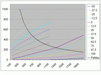
833-data
Hi James,
here's some usefull information gathered from a couple of 833-builders and my own measurements. Maybe it is usefull ?
Anode-voltage (V) / Anode current (mA) / opt impendance (KOhm):
3000 V --- 100 mA --- 20 KOhm
2000 V --- 150 mA --- 10 Kohm
1500 V --- 200 mA --- 8 KOhm
1000 V --- 250 mA --- 5 KOhm
850 V --- 290 mA --- 2 KOhm (to 5 KOhm)
Please, this is guideline only ! But from this small and simple chart you see that you 850 V anode voltage will need a powersupply that delivers 300 mA with spare ! The opt: i would go for something 3,5 ~ 5 kOhm. I never had the chance to listen to a 2 KOhm opt with this tube.
You'll find out that the 833 itself is a pretty flexible tube to use. Of course the required voltages are leading to a somewhat larger powersupply, but it's pretty straightforward. What IS important is the driver. The 833 is huge, so is it's grid. It needs power to bloom ! So design your driver in order to deliver current at a low impendance !
I succeeded with a stepdown interstage from a 300B. Other possibilities:
- triode strapped penthode (KT88 as Wavac does)
- E55L in mu-stage
- 6BM8 through 10:1 interstage (see Bob Danielak)
- i believe Unison845 uses a KT66 as a cothode follower thru a 1:1 interstage ?
Really: the driver is the key design feature in a 833- amplifier.
Yor 6,6 Kohm opt will do. Please check if it can handle the voltages (in combination with the hundred's of mA you're going to pass through).
Happy building !
Reinout
Included a picture of my driver. It's a Valve Art 300B-98C.
Attachments
- Home
- Amplifiers
- Tubes / Valves
- Where are the 833 amps?