Hi All,
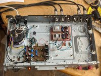
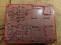
I've been making a plan for a more permanent case for the Iron Pre, and since I'm not going to try out other transformers for the moment (as I had previously intended) I decided to rebuild the transformer and buffer since (a) there's less space in my intended chassis and (b) it had bothered me that the P2P wiring was so crude. So I spent some time taking things apart, and rebuilt the buffer and transformers onto a single veroboard. I made a much better layout, using ZM's pcb design for hints, and I'm much happier with the result. Underside is shown in one of the photos below, as is the same temporary case with the board installed. This also allowed me to have better (and shorter) signal connections, as can be seen compared with the old layout.
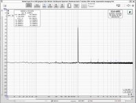
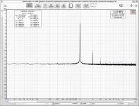
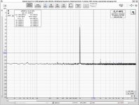
To my surprise, when I measured things on REW again (doing my best to replicate the conditions I had before) the small peaks at odd multiples of the mains 60Hz were (almost) gone. My guess is that this is due to shorter signal paths. I've attached plots that can be compared with the ones I posted earlier, if you're interested. These are just for the R channel, but L is similar. THD is just slightly higher than previously, which confused me until I realised that I'm only measuring the right channel, and I didn't ensure that the L and R jfet pairs weren't swapped, so this is the most likely explanation. (I didn't figure this out until I had disconnected everything, and I didn't want to do it all again.)
I'm pretty happy with this outcome. Not to mention that the board is way prettier... Next step is to redo the PSU board.
ZM: Earlier in the thread you invited us to "make our own" boards from the images you posted, so you have no objection if I use your design to do a homebrew PSU board? I might etch one myself, or maybe send it out; it's probably cheaper. I understand you're doing this for the store, so I'll wait if you'd prefer, although I only need the Good Gemini.
Best
Nigel
I've been making a plan for a more permanent case for the Iron Pre, and since I'm not going to try out other transformers for the moment (as I had previously intended) I decided to rebuild the transformer and buffer since (a) there's less space in my intended chassis and (b) it had bothered me that the P2P wiring was so crude. So I spent some time taking things apart, and rebuilt the buffer and transformers onto a single veroboard. I made a much better layout, using ZM's pcb design for hints, and I'm much happier with the result. Underside is shown in one of the photos below, as is the same temporary case with the board installed. This also allowed me to have better (and shorter) signal connections, as can be seen compared with the old layout.
To my surprise, when I measured things on REW again (doing my best to replicate the conditions I had before) the small peaks at odd multiples of the mains 60Hz were (almost) gone. My guess is that this is due to shorter signal paths. I've attached plots that can be compared with the ones I posted earlier, if you're interested. These are just for the R channel, but L is similar. THD is just slightly higher than previously, which confused me until I realised that I'm only measuring the right channel, and I didn't ensure that the L and R jfet pairs weren't swapped, so this is the most likely explanation. (I didn't figure this out until I had disconnected everything, and I didn't want to do it all again.)
I'm pretty happy with this outcome. Not to mention that the board is way prettier... Next step is to redo the PSU board.
ZM: Earlier in the thread you invited us to "make our own" boards from the images you posted, so you have no objection if I use your design to do a homebrew PSU board? I might etch one myself, or maybe send it out; it's probably cheaper. I understand you're doing this for the store, so I'll wait if you'd prefer, although I only need the Good Gemini.
Best
Nigel
Attachments
everything I post is open source - make it in own way if you wish, make it better if you wish
🙂
🙂
OK, thanks.everything I post is open source - make it in own way if you wish, make it better if you wish
🙂
This temporary chassis doesn't have an ideal setup, I know. The plan (so far as I have one yet) for grounding in the final version is to have a star ground at the output of the PSU, and keep the grounds in each channel separate otherwise. I'm open to other suggestions, though.
move reg farther from Donut. as much close to buffer boards
that's logical, isn't it?
on original boards, regs are ditto to buffers, or vice versa
that's logical, isn't it?
on original boards, regs are ditto to buffers, or vice versa
Yes, it makes sense. The geometry of the new chassis will be rather different. Still planning it.move reg farther form Donut. as much close to buffer boards
that's logical, isn't it?
on original boards, regs are ditto to buffers, or vice versa
I also need to ensure that connections from inputs are short, maybe with relays, but this affects placement of things too.
Speaking of relays, Mouser don't have the RY24W-K in stock. I presume a close relative like the RY-24WZ-K is OK? Did I miss anything?
as far as I see, only difference is lower coil resistance, thus higher coil current
irrelevant for you
irrelevant for you
Thanks.as far as I see, only difference is lower coil resistance, thus higher coil current
irrelevant for you
Hi ZM,move reg farther from Donut. as much close to buffer boards
that's logical, isn't it?
on original boards, regs are ditto to buffers, or vice vers
I tried moving the PSU away from the donut and closer to the boards, as you suggested, however it didn't work out too well; the small peaks at multiples of 60Hz were back. So I moved it back to where it was in the photos above and the small peaks disappeared again. Since your logic is unassailable, and it must be better to have the reg close to the buffer, my best guess is that this is due to careless organisation of the connections between the boards in this temporary chassis. In the final version I'll plan things out better, and hopefully see the benefits of keeping PSU and buffer close.
Another question. What might be the cause of the H2 peak visible at full volume in post #1562? I'm not necessarily looking to get rid of it, but I'm curious. Might it be caused by imperfect matching of the jfets?
most likely - as you said - that you mixed JFets
though - "high" -90db or so bellow fundamental ...... it is well knowing why something is happening, but calling it "high" .......

though - "high" -90db or so bellow fundamental ...... it is well knowing why something is happening, but calling it "high" .......
Thanks. I thought I had them pretty close in idss, but maybe not. Can't remember where I wrote the numbers down and I'd have to turn the music off to measure them again...🙂
I take your point that 90db below is hardly a big concern. Also, I read elsewhere on the site that folks are adding circuitry to make this kind of thing happen, so not really a bad thing anyway, but it's nice to understand things when possible. (Not always the case for me, by a long shot...)
I take your point that 90db below is hardly a big concern. Also, I read elsewhere on the site that folks are adding circuitry to make this kind of thing happen, so not really a bad thing anyway, but it's nice to understand things when possible. (Not always the case for me, by a long shot...)
Playing with H2 usually is just a load line adjustment by varying values of components already there, not requiring much if any added circuitry. Perfect activity for DIY play.

Hi Nelson,
I'm always keen for more "DIY play". 🙂 Perhaps I'll try different jfet pairs, and see what happens. I used little sockets for them instead of soldering them (they are unobtainium, after all!) so it wouldn't be hard.
What I meant by "more circuitry" was the cases I've read about here on diyaudio of people adding your "H2 second harmonic generator" to their amps. (One recent one discussed building it into a class D amp.) Perhaps I wasn't clear.
Best
Nigel
So I spent a couple of hours looking for some 2SK170/2SJ74 pairs in my small stash. I found four or five pairs worth trying; the matches weren't perfect, but were reasonable to try; a typical pair was something like 0.829 and 0.834. I only have about a dozen 2SJ74 left, although rather more 2SK 170, so hoping for better than this is unrealistic. (Besides, these are the same few parts I've already been through to find pairs to make an F5, an M2, and a BA3 preamp, so they're the leftovers now.) In any event, this is close enough to try them out and see what happens. DIY play, as Nelson put it...
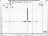
Turns out that the best choice lowered the second harmonic by from about -105dB to about -108dB, with a signal at -17.5dB. Nothing to alert the media about, but enough to show that there's mileage in more careful matching. Also in curve tracing, I imagine, although that may be beyond me at present.
I'm attaching two screenshots in case anyone cares to compare with the ones above.
I'm having a blast with this project, and with REW!
Attachments

Another sketch but for 23x28cm 2U Galaxy:

Donut is far enough or better to go for 3U and place the PCB in vertical on the left side panel?

Donut is far enough or better to go for 3U and place the PCB in vertical on the left side panel?
10VA Donut is good enough
20VA max
no other way than trying it
only then you'll know will it hum or not
it really depends of quality - how good Donut is and how good magnetic shielding is
I remember ....... Donuts Pa gave me to assemble his Plankey ......... they're inducung hum (only in SE mode ) even if moved all the way to Beach
- Home
- Amplifiers
- Pass Labs
- What's wrong with the kiss, boy?